Mould Tools Introduction
advertisement
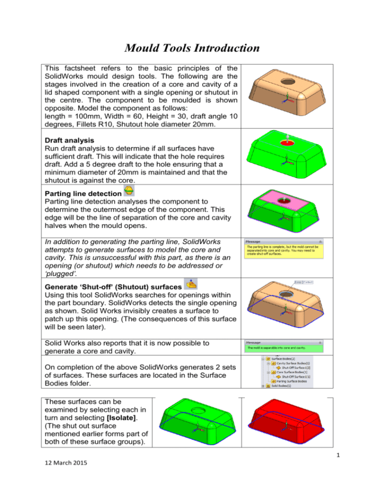
Mould Tools Introduction This factsheet refers to the basic principles of the SolidWorks mould design tools. The following are the stages involved in the creation of a core and cavity of a lid shaped component with a single opening or shutout in the centre. The component to be moulded is shown opposite. Model the component as follows: length = 100mm, Width = 60, Height = 30, draft angle 10 degrees, Fillets R10, Shutout hole diameter 20mm. Draft analysis Run draft analysis to determine if all surfaces have sufficient draft. This will indicate that the hole requires draft. Add a 5 degree draft to the hole ensuring that a minimum diameter of 20mm is maintained and that the shutout is against the core. Parting line detection Parting line detection analyses the component to determine the outermost edge of the component. This edge will be the line of separation of the core and cavity halves when the mould opens. In addition to generating the parting line, SolidWorks attempts to generate surfaces to model the core and cavity. This is unsuccessful with this part, as there is an opening (or shutout) which needs to be addressed or ‘plugged’. Generate ‘Shut-off’ (Shutout) surfaces Using this tool SolidWorks searches for openings within the part boundary. SolidWorks detects the single opening as shown. Solid Works invisibly creates a surface to patch up this opening. (The consequences of this surface will be seen later). Solid Works also reports that it is now possible to generate a core and cavity. On completion of the above SolidWorks generates 2 sets of surfaces. These surfaces are located in the Surface Bodies folder. These surfaces can be examined by selecting each in turn and selecting [Isolate]. (The shut out surface mentioned earlier forms part of both of these surface groups). 1 12 March 2015 Generating parting surfaces The simplest way to generate the parting surface, the separation between core and cavity halves of the mould, it to radiate the parting line outwards. This is achieved by selecting the Parting Surface command, then using the ‘perpendicular to pull’ option, specifying a radial distance for the surface to extend. Generating the mould base To generate the mould base a rectangular sketch is drawn representing the size of the mould perpendicular to the line of pull. To successfully create the mould base, it is necessary that the parting surface extends beyond the dimensions of the mould in all directions. On completing of this step, Exit the sketch. Finally select the Split Tool command and select the sketch defining the mould outline. Using this sketch, combined with the contents of the Core surface Cavity surface Parting surface and a core and cavity block thickness specified by the user, Solid Works creates the mould tool required to mould the component. The finished tool should look as shown opposite. Surface bodies are central to the mould generating process. In order to generate a split mould three sets of surfaces are required, Cavity surfaces, Core surfaces, Parting surfaces. All three sets of surfaces must meet at t common point. Summary of Mould creation procedure:STEP 1: Run draft analysis to ensure all surfaces have sufficient draft. STEP 2: Scale part to compensate for shrinkage. STEP 3: Generate Parting Line to determine the outermost edge of the component STEP 4: Generate Shut-offs surfaces - only required if the part has internal openings. STEP 5: Generate parting surfaces. The may be generated automatically or manually. STEP 6: Generate the split tool or ‘Tooling Split’ – this creates a core and cavity block. 2 12 March 2015
