Voltage divider tutorial outline
advertisement
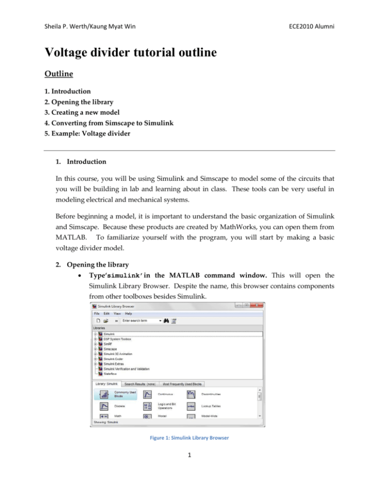
Sheila P. Werth/Kaung Myat Win ECE2010 Alumni Voltage divider tutorial outline Outline 1. Introduction 2. Opening the library 3. Creating a new model 4. Converting from Simscape to Simulink 5. Example: Voltage divider 1. Introduction In this course, you will be using Simulink and Simscape to model some of the circuits that you will be building in lab and learning about in class. These tools can be very useful in modeling electrical and mechanical systems. Before beginning a model, it is important to understand the basic organization of Simulink and Simscape. Because these products are created by MathWorks, you can open them from MATLAB. To familiarize yourself with the program, you will start by making a basic voltage divider model. 2. Opening the library Type‘simulink’in the MATLAB command window. This will open the Simulink Library Browser. Despite the name, this browser contains components from other toolboxes besides Simulink. Figure 1: Simulink Library Browser 1 Sheila P. Werth/Kaung Myat Win ECE2010 Alumni The library is organized into several different tool boxes. Each toolbox in composed of specific components. Circuit building components can be found by expanding Simscape and looking in the foundations library or the SimElectronics library. These components work with physical signals. Physical signals have units, while Simulink signals do not. Simulink blocks are used to process and view data. To view and analyze the results of a model, you must convert the physical signal in your Simscape model to a Simulink signal. 3. Creating a new model To open a new model click on the ‘new model’ button just below the ‘file’ button in the Simulink Library Browser.You can drag components from the Simulink Library Browser into the new modelwindow. Figure 2: How to Create New Model To save a model, click or you can go to File Savefile_name.mdl . Be sure to save it in a location where you can retrieve later.Save your file asvoltage_divider.mdl. In order to run, every Simscape model must have a solver configuration block. This block can be connected anywhere in the model. Because every model also needs an electrical reference (ground), it is good practice to begin by adding Figure 3: Solver with Electrical and connecting both of these blocks in your Reference model. Drag a solver configuration block and an electrical reference from the library into your model. Connect them. i. The solver configuration block can be found in the library browser: Simscape Utilities Solver Configuration ii. The electrical reference (ground) can also be found in the library browser: Simscape Foundation Library Electrical Elements Electrical Reference Blocks can be connected by dragging your curser from one input or output node to another. A complete connection will appear black while an incomplete 2 Sheila P. Werth/Kaung Myat Win ECE2010 Alumni connection will appear red. Do not let red segments stay in your model because it will not run. Simulink blocks do not connect directly to Simscape blocks. To connect them, see instructions in part 4. 4. Creating the voltage divider Drag and drop two resistors from the library into your newly created model window. You can change the format or properties by right-clicking the model. Right-click the resistor model, choose FormatRotate BlockClockwise to rotate the resistor. You can also use Crtl+R shortcut to do the same action. Drag a source from the library into your model to Figure 4: Solver, Ground, and power the resistors. Connect the components as shown Two Resistors in Figure 5. There are two kinds of electrical sources in the Simscape library. The first one is under Foundation Library ElectricalElectrical Sources. The second one is under Foundation LibrarySimElectronicsSources. You can use either DC voltage source or Generic Battery. The only difference is that when you use Generic Battery, you can define the internal resistance and battery charging capacity in Generic Battery. You should use DC voltage Figure 5: Voltage divider source under Electrical Sources for simplicity. By configuration double clicking, you can access a model’s parameters and you can change the parameters according to your needs. Clicking in the parameters window directs you to online help page. Connect DC voltage source to two resistors in series. Make sure that the Solver Configuration and Electrical Reference are connected to your circuit as shown in Figure 5. Simscape portion of your model. You have now built the To run the model, you will need to convert from Simscape to Simulink. 5. Converting from Simscape to Simulink As discussed above, a Simscape model will create a physical signal. Examples of physical signals include voltage, current, speed, etc. These signals have units like Volts, Amps, Meters/s etc. 3 Sheila P. Werth/Kaung Myat Win ECE2010 Alumni To view the results of your model you must convert to a Simulink signal. A Simulink signal is simply numerical data with no units. These are the steps to converting from Simscape physical signal to a Simulink signal: i. Connect a voltage sensor across the ports that you want to measure. Electrical sensors include voltage and current sensors. There are other types of sensors you may use in the future. Simscape Foundation Library Electrical Electrical Sensors ii. Connect a PS-Simulink Converter block to the sensor block. Simscape Utilities PS-Simulink Converter iii. Connect a Display block to view your results.There are other sinks that you will use in the future. Simulink Sinks Display Figure 6: The Complete Model of Voltage Divider 6. Simulating the model Change the resistor values and voltage source by double clicking on the block and typing the desired value. Change the configuration parameters as shown in Figure 7 shown below. Set Stop time to 10. This is the amount of time you want the model to be simulated. Since this circuit is only a DC analysis, the stop time does not matter and we will leave it as it is. 4 Sheila P. Werth/Kaung Myat Win ECE2010 Alumni Set Max step size to 1. Normally, the ‘auto’ step size is defined as the total simulation time divided by 50, which would be equal to be 0.2. Since we are doing DC analysis, we would not need this much step size as the values we get will be constant over time. Set the solver to ode23t (mod. stiff/Trapezoid). Since the model is stiff as it contains Simscape components, we will use one of the solvers (ode23t, ode15s or ode14x (fixed-step)) preferred for the stiff models. Press OK button after you have changed the fields as shown in Figure 7. Figure 7: Configuration Parameters for the voltage divider model To run the model, click from the tool bar to simulate the model. You can also hit Ctrl+T or go to SimulationStart from the task bar. Does the answer meet your expectations? 5


