MIPS instruction formats
advertisement
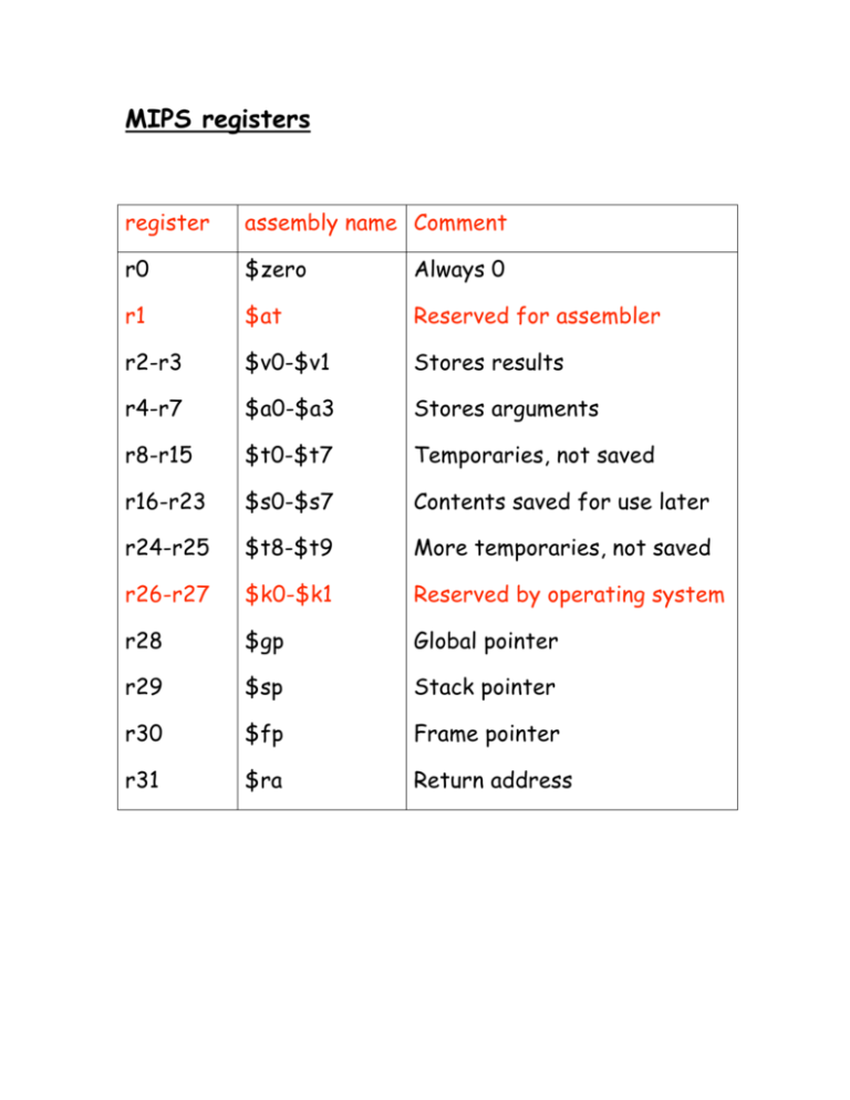
MIPS registers register assembly name Comment r0 $zero Always 0 r1 $at Reserved for assembler r2-r3 $v0-$v1 Stores results r4-r7 $a0-$a3 Stores arguments r8-r15 $t0-$t7 Temporaries, not saved r16-r23 $s0-$s7 Contents saved for use later r24-r25 $t8-$t9 More temporaries, not saved r26-r27 $k0-$k1 Reserved by operating system r28 $gp Global pointer r29 $sp Stack pointer r30 $fp Frame pointer r31 $ra Return address MIPS insruction formats Instruction “add” belongs to the R-type format. opcode rs rt rd 6 5 5 5 src src add $s1, $s2, $t0 shift amt function 5 6 dst will be coded as 0 18 8 17 6 5 5 5 0 32 5 6 The “function” field is an extension of the opcode, and they together determine the operation. Note that “sub” has a similar format. Instruction “lw” (load word) belongs to I-type format. opcode rs rt 6 5 5 16 base dst offset lw $t0, 32($s3) address will be coded as 35 19 8 6 5 5 32 16 Both “lw” and “sw” (store word) belong to I-format. MIPS has (fortunately) only three different instruction formats. The operation codes determine the format. This is how the control unit interprets the instructions. What is an Assembler? Assembly Language Assembler Machine Language lw t0, 32($s3) Consists of 0’s add $s1, $s2, $t0 and 1’s only If you know the instruction formats, then you can translate it. The machine language consists of 0’s and 1’s Think about these 1. How will you load a constant into a memory location (i.e. consider implementing x :=3) 2. How will you implement x:= x+1 in assembly language? 3. Why is the load (and store too) instruction so “crooked?” 4. How will you load a constant (say 5) into a register? Pseudo-instructions These are simple assembly language instructions that do not have a direct machine language equivalent. During assembly, the assembler translates each psedudoinstruction into one or more machine language instructions. Example move $t0, $t1 # $t0 ! $t1 The assembler will translate it to add $t0, $zer0, $t1 We will see more of these soon. Loading a 32-bit constant into a register lui $s0, 42 # load upper-half immediate ori $s0, $s0, 18 # (one can also use andi) What is the end result? Logical Operations Shift left srl Shift right sll Bit-by-bit AND and, andi (and immediate) opcode rs rt rd 6 5 5 5 src src shift amt function 5 6 dst sll $t2, $s0, 4 means $t2 = $s0 << 4 bit position (s0 = r16, t2 = r10) 0 6 0 16 10 5 5 5 4 5 0 6 s0 = 0000 0000 0000 0000 0000 0000 0000 1001 t2 = 0000 0000 0000 0000 0000 0000 1001 0000 Why are these instructions useful?
