Lab 3.5.2: Challenge Frame Relay Configuration
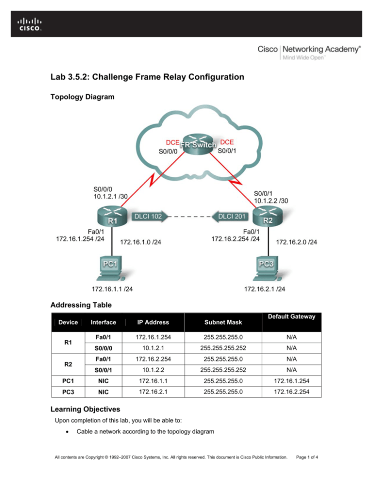
Topology Diagram
Addressing Table
Default Gateway
Device
Interface
IP Address
Subnet Mask
Fa0/1
172.16.1.254
255.255.255.0
N/A
S0/0/0
10.1.2.1
255.255.255.252
N/A
Fa0/1
172.16.2.254
255.255.255.0
N/A
S0/0/1
10.1.2.2
255.255.255.252
N/A
PC1
NIC
172.16.1.1
255.255.255.0
172.16.1.254
PC3
NIC
172.16.2.1
255.255.255.0
172.16.2.254
R1
R2
Learning Objectives
Upon completion of this lab, you will be able to:
•
Cable a network according to the topology diagram
All contents are Copyright © 1992–2007 Cisco Systems, Inc. All rights reserved. This document is Cisco Public Information.
Page 1 of 4
CCNA Exploration
Accessing the WAN: Frame Relay
Lab 3.5.2: Challenge Frame Relay Configuration
•
Erase the startup configuration and reload a router to the default state
•
Perform basic configuration tasks on a router
•
Configure and activate interfaces
•
Configure EIGRP routing on all routers
•
Configure Frame Relay encapsulation on all serial interfaces
•
Configure a Frame Relay PVC
•
Intentionally break and restore a Frame Relay PVC
•
Configure Frame Relay subinterfaces
•
Intentionally break and restore the PVC
Scenario
In this lab, you will configure Frame Relay using the network shown in the topology diagram. If
you need assistance, refer to the Basic Frame Relay lab. However, try to do as much on your
own as possible.
Task 1: Prepare the Network
Step 1: Cable a network that is similar to the one in the topology diagram.
Step 2: Clear any existing configurations on the routers.
Task 2: Perform Basic Router Configuration
Configure the R1, R2, and R3 routers according to the following guidelines:
•
Configure the router hostname.
•
Disable DNS lookup.
•
Configure an EXEC mode password.
•
Configure a message-of-the-day banner.
•
Configure a password for console connections.
•
Configure synchronous logging.
•
Configure a password for vty connections.
Task 3: Configure IP Addresses
Step 1: Configure IP addresses on all links according to the addressing table.
Step 2: Verify IP addressing and interfaces.
Step 3: Activate Ethernet interfaces of R1 and R2. Do not activate the serial interfaces.
Step 3: Configure the Ethernet interfaces of PC1 and PC3.
Step 4: Test connectivity between the PCs and their local routers.
Task 4: Configure EIGRP on Routers R1 and R2
All contents are Copyright © 1992–2007 Cisco Systems, Inc. All rights reserved. This document is Cisco Public Information.
Page 2 of 4
CCNA Exploration
Accessing the WAN: Frame Relay
Lab 3.5.2: Challenge Frame Relay Configuration
Step 1: Enable EIGRP on R1 and R2 for all subnets.
Task 5: Configure Frame Relay PVC Between R1 and R2
Step 1: Configure interfaces on FR-Switch to create the PVC between R1 and R2.
Use the DLCIs in the topology diagram.
Step 2: Configure physical interfaces on R1 and R2 for Frame Relay encapsulation.
Do not automatically discover IP addresses on the far end of links. Activate the link after full
configuration.
Step 3: Configure Frame Relay maps on R1 and R2 with proper DLCIs. Enable broadcast
traffic on the DLCIs.
Step 4: Verify end-to-end connectivity using PC1 and PC2.
Task 6: Intentionally Break the PVC and Then Restore It
Step 1: By a means of your choosing, break the PVC between R1 and R2.
Step 2: Restore full connectivity to your network.
Step 3: Verify full connectivity to your network.
Task 7: Configure Frame Relay Subinterfaces
Step 1: Remove the IP address and frame map configuration from the physical interfaces
on R1 and R2.
Step 2: Configure Frame Relay point-to-point subinterfaces on R1 and R2 with the same IP
addresses and DLCI used earlier on the physical interfaces.
Step 3: Verify full end-to-end connectivity.
Task 8: Intentionally Break the PVC and Then Restore It
Step 1: Break the PVC using a different method than you used in Task 6.
Step 2: Restore the PVC.
Step 3: Verify full end-to-end connectivity.
Task 9: Document the Router Configurations
On each router, issue the show run command and capture the configurations.
Task 10: Clean Up
Erase the configurations and reload the routers. Disconnect and store the cabling. For PC hosts
All contents are Copyright © 1992–2007 Cisco Systems, Inc. All rights reserved. This document is Cisco Public Information.
Page 3 of 4
CCNA Exploration
Accessing the WAN: Frame Relay
Lab 3.5.2: Challenge Frame Relay Configuration
that are normally connected to other networks (such as the school LAN or to the Internet),
reconnect the appropriate cabling and restore the TCP/IP settings.
All contents are Copyright © 1992–2007 Cisco Systems, Inc. All rights reserved. This document is Cisco Public Information.
Page 4 of 4


