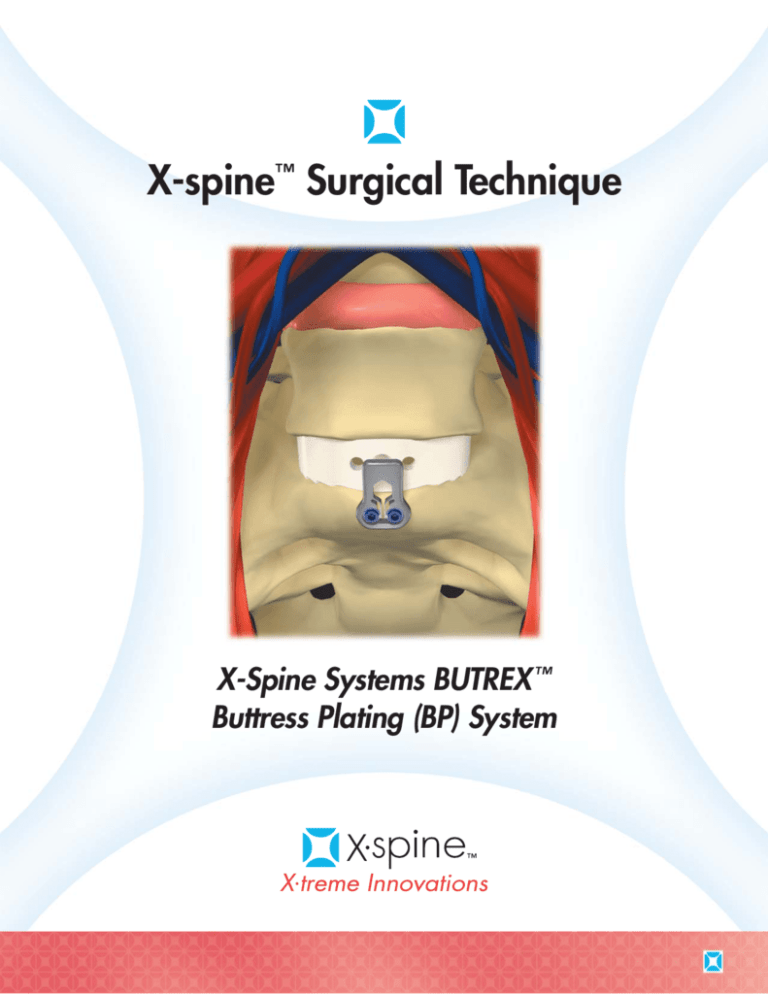
X-spine™ Surgical Technique
X-Spine Systems BUTREX ™
Buttress Plating (BP) System
Inside Front Cover
Blank
X-Spine Systems BUTREX™ Buttress Plating (BP) System
General Description
Indications for Use
The X-Spine Butrex Plating (BP) System is intended for
anterior screw fixation to the L1 to S1 spine. The BP
System consists of a variety of shapes and sizes of
bone plates and screws. The components are
manufactured from titanium alloy (Ti 6Al 4V ELI) as
described by ASTM F136. Components of the X-Spine
BP System should not be used with components from
any other system or manufacturer. The X-Spine BP
System components are provided non-sterile. The
products need to be steam sterilized by the hospital
prior to use. The Butrex Buttress Plating system is only
intended to be used in the presence of supplemental
posterior fixation, such as pedicle screw fixation.
The Butrex Buttress Plating System is intended for
anterior intravertebral body screw fixation/attachment
to the L1-S1 spine over one vertebral body extending
onto the adjacent intervertebral space. Due to
variations in the anatomy, the plate is designed for
applications caudal to the bifurcation of the great
vessels. Specifically, the device is intended for
stabilization and buttressing of bone graft over one
motion segment following anterior structural
reconstruction for degenerative disc disease (DDD).
DDD is defined as follows: back pain of discogenic
origin with the degeneration of the disc confirmed by
history and radiographic studies.
Warnings
Precautions
1. This device is not approved for screw attachment
to the posterior elements (pedicles) of the cervical,
thoracic, or lumbar spine.
The X-Spine BP System should only be implanted by
surgeons who are fully experienced in the use of such
implants and the required specialized spinal surgery
techniques. Further, the proper selection and
compliance of the patient will greatly affect the results.
The surgeon should consider the patient conditions
(e.g., smoker, malnutrition, obesity, alcohol and drug
abuse, poor muscle and bone quality), which may
impact system performance. Due to the presence of
implants, interference with roentgenographic, CT,
and/or MR imaging will result.
2. Mixing of dissimilar metals can accelerate the
corrosion process. Stainless steel and titanium
implants must NOT be used together in building
a construct. The X-Spine BP System should not be
used with components from any other system or
manufacturer. As with all orthopaedic implants, the
X-Spine BP System should not be reused after use
in an implant or prior to sterilization.
The X-Spine BP System is only a temporary implant
used for the anterior buttressing of a lumbar
intervertebral bone graft. This device system is not
intended to be used as a means of spinal support
or fixation. Bone grafting must be part of the spinal
fusion procedure in which the X-Spine BP System is
utilized. Use of this product without a bone graft or
in cases that develop into a nonunion will not be
successful. The spinal implant cannot withstand body
loads. In this event, bending, loosening, disassembly
and or breakage of the device will eventually occur.
Bone cement should not be used since this material
will make removal of the components difficult or
impossible. The heat from the curing process may
cause neurological damage and bone necrosis.
3. To avoid the risk of vascular injury, the plate must
be placed caudal to the bifurcation of the great
vessels.
4. The Butrex Plate must be placed such that the tip
of the plate does not impinge upon the adjacent
vertebral body. Such placement may result in
abnormal plate loading and device loosening or
failure.
5. The Butrex Buttress Plating system is only intended
to be used in the presence of supplemental
posterior fixation, such as pedicle screw fixation.
Failure to utilize the Butrex system with
supplemental posterior fixation may result in
abnormal loading and product failure.
Please refer to the Package Insert for a comprehensive
listing of warnings and precautions.
1
X-spine™ Surgical Technique
X-Spine Systems BUTREX ™ Buttress Plating (BP) System
This publication recommends procedures for using X-spine products and instruments. The guidance it offers is for surgeon consideration, but, as with any technical
guide, the surgeon must evaluate the specific requirements of the patient, making appropriate adjustments as needed.
1. Approach
The anterior lumbar spine is approached via a
standard exposure of the retroperitoneal space.
The great vessel bifurcation should be identified
and appropriate retraction performed so that
there is adequate exposure of the disc space
to be fused and the adjacent vertebral bodies.
2. Discectomy
Once adequate exposure of the disc space is
obtained and the correct level confirmed by
radiography, an anterior discectomy is performed.
2
3. Allograft Placement
An appropriately sized allograft spacer is placed
into the disc space. A load bearing cortical
allograft, such as a femoral ring allograft (FRA),
is placed into the disc space.
4. Allograft Position
Confirmation
The position of the allograft should be
confirmed, as well as the adequate exposure
of the anterior vertebral bodies. The great
vessels and iliac vessels should be retracted in
preparation for the Butrex plate. The plate must
be placed caudal to the great vessel bifurcation.
5. Plate Sizing
The appropriate sized plate should be selected
with the plate holes directly anterior to the
midpoint of the vertebrae caudal to the fused
level. Plates are provided in 22mm and 26mm
lengths.
Warning: The Butrex Plate must be placed such
that the tip of the plate does not impinge upon the
adjacent vertebral body. Such placement may
result in abnormal plate loading and device
loosening or failure.
3
6. Drill Guide
Single and Double Barrel drill guides are
provided for the placement of screws. The drill
guide should engage the plate. 20, 22 and 24
mm drill bits are provided to drill pilot holes. A
quick-connect handle may be connected to the
drill bits for drilling.
7. Drilling
The drill bit should be driven until it stops at the
upper portion of the drill guide.
8. Thread Tapping
A 4.3mm thread tap is provided to place threads
into the pilot hole.
4
9. Screw Placement
After pilot hole tapping, a screw can be placed,
using the provided self-retaining hex screwdriver.
Screws are provided in the following sizes:
4.3mm Fixed Screw - 20mm
4.3mm Fixed Screw - 22mm
4.3mm Fixed Screw - 24mm
4.5mm Fixed Screw - 20mm
4.5mm Fixed Screw - 22mm
4.5mm Fixed Screw - 24mm
Note that the screws are to be placed centrally on
the ventral surface of the vertebral body. Screws
should be placed within the spinal midline and
centrally in the craniocaudal axis of the ventral
vertebral body. This minimizes the risk of screw
placement into the weaker vertebral endplate.
10. Final Position Confirmation
The X-Spine BP incorporates resilient locking arms
with tabs which seat on a corresponding locking
surface of the placed bone screw head. After
placement of the screw, the resilient arm should be
visualized with the locking tab positioned over the
medial portion of the screw head.
5
11. Posterior Fixation
The Butrex Buttress Plating system is only intended
to be used in the presence of supplemental
posterior fixation, such as pedicle screw fixation.
After placement of the intervertebral graft and
Butrex plate, normal closure of the anterior
approach should be performed. The patient
should then be repositioned and a posterior
fixation construct performed. Failure to utilize the
Butrex system with supplemental posterior fixation
may result in abnormal loading and product
failure. See an example of a rod and pedicle
screw based posterior fixation system at right.
12. Plate Removal (if required)
The screw removal instrument is placed into the
plate slots adjacent to the screw sockets. This
flexes the locking arms inward and allows for
screws to be removed using the screw driver.
Please note that the contoured side of the removal
tool should be oriented in the cranial direction.
Note: Locking mechanism should only undergo
three locking cycles. If three locking cycles are
exceeded, it is recommended to replace the
Butrex plate.
6
BUTREX® Buttress Plating System
Instruments
3-sided Silicone Handle w/AO connector – #N60000178
ButreX Screw Driver – #X023-0050
ButreX Screw Removal Device – #X023-0055
Fixation Pin Impactor – #N60001054
ButreX Bone Awl – #X023-0060
20mm ButreX Drill – #X023-0031
22mm ButreX Drill – #X023-0032
24mm ButreX Drill – #X023-0033
ButreX Single Barrel Guide – #X023-0070
ButreX Double Barrel Guide – #X023-0040
ButreX Plate Holder – #X023-0100
4.3mm ButreX Tap – #X023-0045
7
Notes
8
Inside Back Cover
Blank
WARNING: In the USA, this product has labeling limitations.
See package insert for complete information.
CAUTION: Federal Law (USA) restricts this device to sale by or
on the order of a physician.
X-spine™ the X-spine logo and BUTREX® are trademarks of
X-spine Systems, Inc.
Products Patented and Patents Pending
All products are not currently available in all markets.
© 2008 X-spine Systems, Inc., All rights reserved.
X023-2002 Rev A. 9743 xM 7/08 TG/x
X-spine Systems, Inc.
452 Alexandersville Rd., Miamisburg, OH 45342
Phone: 800-903-0640 • Direct: 937-847-8400 • Fax: 937-847-8410
www.x-spine.com

