MEG381.LABS.LVDT
advertisement
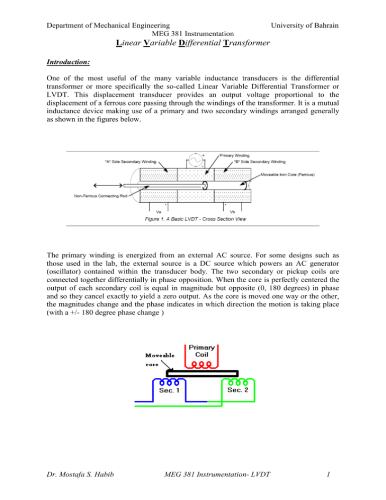
Department of Mechanical Engineering MEG 381 Instrumentation University of Bahrain Linear Variable Differential Transformer Introduction: One of the most useful of the many variable inductance transducers is the differential transformer or more specifically the so-called Linear Variable Differential Transformer or LVDT. This displacement transducer provides an output voltage proportional to the displacement of a ferrous core passing through the windings of the transformer. It is a mutual inductance device making use of a primary and two secondary windings arranged generally as shown in the figures below. The primary winding is energized from an external AC source. For some designs such as those used in the lab, the external source is a DC source which powers an AC generator (oscillator) contained within the transducer body. The two secondary or pickup coils are connected together differentially in phase opposition. When the core is perfectly centered the output of each secondary coil is equal in magnitude but opposite (0, 180 degrees) in phase and so they cancel exactly to yield a zero output. As the core is moved one way or the other, the magnitudes change and the phase indicates in which direction the motion is taking place (with a +/- 180 degree phase change ) Dr. Mostafa S. Habib MEG 381 Instrumentation- LVDT 1 Objectives: Determination the end deflection and stiffness of the cantilever. Theory of Operation LVDT is much like any other transformer in that it consists of a primary coil, secondary coils, and a magnetic core. An alternating current, known as the carrier signal, is produced in the primary coil. The changing current in the primary coil produces a varying magnetic field around the core. This magnetic field induces an alternating (AC) voltage in the secondary coils that are in proximity to the core. As with any transformer, the voltage of the induced signal in the secondary coil is linearly related to the number of coils. The basic transformer relation is: Where: Vout is the voltage at the output, Vin is the voltage at the input, Nout is the number of windings of the output coil, and Nin is the number of windings of the input coil. As the core is displaced, the number of coils in the secondary coil exposed to the coil changes linearly. Therefore the amplitude of the induced signal varies linearly with displacement. The LVDT indicates direction of displacement by having the two secondary coils whose outputs are balanced against one another. The secondary coils in an LVDT are connected in the opposite sense (one clockwise, the other counter clockwise). Thus when the same varying magnetic field is applied to both secondary coils, their output voltages have the same amplitude but differ in sign. The outputs from the two secondary coils are summed together, usually by simply connecting the secondary coils together at a common center point. At an equilibrium position (generally zero displacement) a zero output signal is produced. The induced AC signal is then demodulated so that a DC voltage that is sensitive to the amplitude and phase of the AC signal is produced. Procedure:- 1-Use scale and a voltmeter as given in the lab and we determine LVDT core location (x) and its corresponding output voltage (v). 2- Tabulate the measured (x) and (v). 3- Repeat for many core location covering the core full range. 4- plot the relationship of (x) versus (v) 5- Obtain the null position of the core, hence; plot the (x) versus v. 6- identify the linear and nonlinear regions 7- Remove the nonlinear points from your data. 8- Obtain the best fit (linear regression) for the linear region. 9- Determine the slop (=sensitivity in mV of the measured v per Volt of the input per mm of (x)) of the LVDT. 10- Draw conclusions. Dr. Mostafa S. Habib MEG 381 Instrumentation- LVDT 2
