LVDT
advertisement
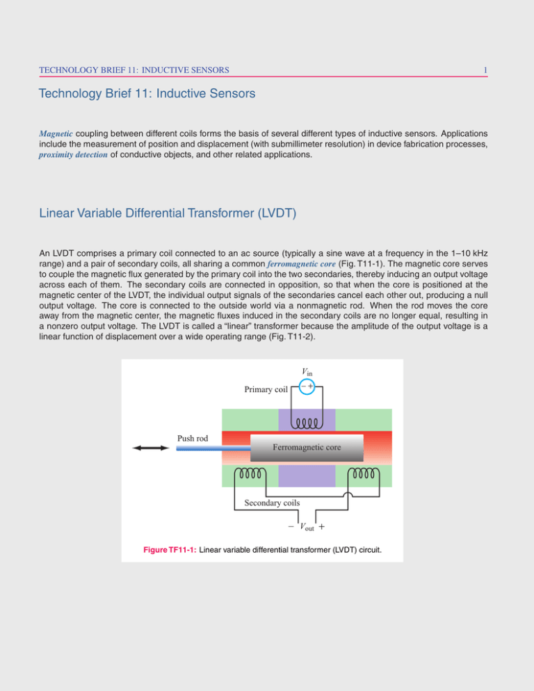
TECHNOLOGY BRIEF 11: INDUCTIVE SENSORS 1 Technology Brief 11: Inductive Sensors Magnetic coupling between different coils forms the basis of several different types of inductive sensors. Applications include the measurement of position and displacement (with submillimeter resolution) in device fabrication processes, proximity detection of conductive objects, and other related applications. Linear Variable Differential Transformer (LVDT) An LVDT comprises a primary coil connected to an ac source (typically a sine wave at a frequency in the 1–10 kHz range) and a pair of secondary coils, all sharing a common ferromagnetic core (Fig. T11-1). The magnetic core serves to couple the magnetic flux generated by the primary coil into the two secondaries, thereby inducing an output voltage across each of them. The secondary coils are connected in opposition, so that when the core is positioned at the magnetic center of the LVDT, the individual output signals of the secondaries cancel each other out, producing a null output voltage. The core is connected to the outside world via a nonmagnetic rod. When the rod moves the core away from the magnetic center, the magnetic fluxes induced in the secondary coils are no longer equal, resulting in a nonzero output voltage. The LVDT is called a “linear” transformer because the amplitude of the output voltage is a linear function of displacement over a wide operating range (Fig. T11-2). Vin _ Primary coil + Push rod Ferromagnetic core Secondary coils _ V out + Figure TF11-1: Linear variable differential transformer (LVDT) circuit. 2 TECHNOLOGY BRIEF 11: INDUCTIVE SENSORS Amplitude and Phase Output Phase Amplitude −10 −5 0 5 Distance Traveled 10 Figure TF11-2: Amplitude and phase responses as a function of the distance by which the magnetic core is moved away from the center position. The cutaway view of the LVDT model in Fig. T11-3 depicts a configuration in which all three coils—with the primary straddled by the secondaries—are wound around a glass tube that contains the magnetic core and attached rod. Sample applications are illustrated in Fig. T11-4. Stainless steel housing Rod Magnetic core Primary coil Secondary coils Figure TF11-3: Cutaway view of LVDT. Electronics module TECHNOLOGY BRIEF 11: INDUCTIVE SENSORS 3 Sagging beam LVDT Float LVDT FigureTF11-4: LVDT for measuring beam deflection and as a fluid-level gauge. Eddy-Current Proximity Sensor The transformer principle can be applied to build a proximity sensor in which the output voltage of the secondary coil becomes a sensitive indicator of the presence of a conductive object in its immediate vicinity (Fig. T11-5). When an object is placed in front of the secondary coil, the magnetic field of the coil induces eddy (circular) currents in the object, which generate magnetic fields of their own having a direction that opposes the magnetic field of the secondary coil. The reduction in magnetic flux causes a drop in output voltage, with the magnitude of the change being dependent on the conductive properties of the object and its distance from the sensor. _ Vin + Primary coil _ Vout + Eddy currents Sensing coil Conductive object Figure TF11-5: Eddy-current proximity sensor.


