Experiment
advertisement
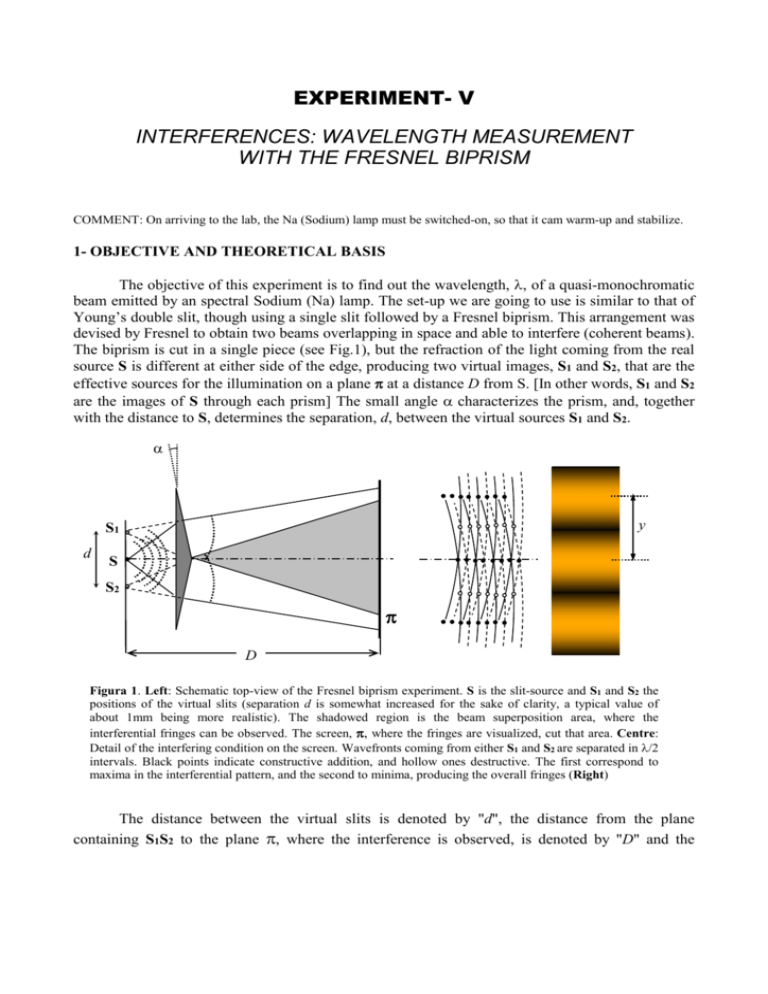
EXPERIMENT- V INTERFERENCES: WAVELENGTH MEASUREMENT WITH THE FRESNEL BIPRISM COMMENT: On arriving to the lab, the Na (Sodium) lamp must be switched-on, so that it cam warm-up and stabilize. 1- OBJECTIVE AND THEORETICAL BASIS The objective of this experiment is to find out the wavelength, of a quasi-monochromatic beam emitted by an spectral Sodium (Na) lamp. The set-up we are going to use is similar to that of Young’s double slit, though using a single slit followed by a Fresnel biprism. This arrangement was devised by Fresnel to obtain two beams overlapping in space and able to interfere (coherent beams). The biprism is cut in a single piece (see Fig.1), but the refraction of the light coming from the real source S is different at either side of the edge, producing two virtual images, S1 and S2, that are the effective sources for the illumination on a plane at a distance D from S. [In other words, S1 and S2 are the images of S through each prism] The small angle characterizes the prism, and, together with the distance to S, determines the separation, d, between the virtual sources S1 and S2. y S1 d S S2 D Figura 1. Left: Schematic top-view of the Fresnel biprism experiment. S is the slit-source and S1 and S2 the positions of the virtual slits (separation d is somewhat increased for the sake of clarity, a typical value of about 1mm being more realistic). The shadowed region is the beam superposition area, where the interferential fringes can be observed. The screen, , where the fringes are visualized, cut that area. Centre: Detail of the interfering condition on the screen. Wavefronts coming from either S1 and S2 are separated in /2 intervals. Black points indicate constructive addition, and hollow ones destructive. The first correspond to maxima in the interferential pattern, and the second to minima, producing the overall fringes (Right) The distance between the virtual slits is denoted by "d", the distance from the plane containing S1S2 to the plane , where the interference is observed, is denoted by "D" and the distance between two consecutive bright fringes is denoted by "y". Then, from the interference condition the following relation is obtained: y = D/ d or equivalently = yd / D and this allows us to obtain the value of from the measurement of y, D, and d. 2- MATERIALS • Optical bench with linear scale. • Slit with variable width. • Sodium (Na) gas spectral lamp. • Fresnel biprism with adjustable holder. • An eyepiece with a reference line on the focusing plane. It is mounted in a holder with a lateral movement of good precision (one hundredth of a millimetre: 0,01mm=10m). • A converging lens (to help measure the distance d = S1S2) • A microscope with a reference cross to measure the distance D. 3- ALIGNMENT AND EXPERIMENTAL SET-UP 1.-Place the Sodium (Na) lamp so that it conveniently illuminates the slit. 2.-Place all the components in their approximate positions. This means that, for the raw eye, they are all hanging on the same axis, at the same height and perpendicular to the axis of the bench. 3.-Focus the eyepiece of the microscope (that can move inside its frame, where it fits into) on its reference cross (drawn on a thin glass slide inside the metal cylinder), and rotate that frame so that one cross line gets vertical. 4.-Focusing the microscope on the slit, align the vertical reference with it. This implies moving the microscope along the bench for focusing, vertically to see the slit centred in the field of view, and transversely to make the vertical line approximately overlap with the slit. From this moment, the microscope will serve as a transversal reference for other elements. Put apart the microscope and place the biprism near the slit (at a few centimetres). Now we focus the microscope on the biprism and try to observe the edge, seen as a vertical bright line. It is the biprism that must be moved transversely now till the vertical reference line overlaps with the image of the edge. To get a precise overlapping, rotate by hand the reference cross of the microscope. It is important to achieve a good overlapping in this part. 5.-We now put apart the biprism (handling it with great care) and focus the microscope again on the slit, moving carefully the microscope on the bench. We rotate the slit, either with the coarse (unblocked screw and hand rotation) or with the fine adjustment wheel (blocked screw), till it gets parallel to the vertical reference of the microscope. It may be necessary now to make a new transversal movement of the slit, to achieve a perfect overlapping. After this, the slit and the biprism edge should be well aligned. This can be checked with the microscope, and steps 4 and 5 might be repeated if the result is not considered satisfactory. 6.-Place the converging lens on the bench, and try to centre it transversely so that it gets approximately aligned with the microscope. (There is no need of looking through it). 7.-Now we must centre the eyepiece with which to observe the actual interference fringes. This eyepiece must focus on a faint cross drawn on a thin glass slide, mounted in the same frame than the eyepiece itself. (This slide represent the plane where the interference fringes are formed). We first take the eyepiece out of its frame, and focus the microscope on the faint cross. This cross must be rotated and moved transversely and in height on its holder, so that it gets centred with the microscope reference. We can put again the eyepiece, focused on its faint reference cross. 8.- We now can improve a little bit the alignment performed so far. We put the slit, then the biprism and then the eyepiece, at a certain distance, and look through it. If the fringes don’t have good visibility (high contrast), we can either rotate the slit slowly, or make it narrower (with the open/close screw). This operation is properly carried out by two people. 9.- A final check can be performed as follows: Put the eyepiece close to the biprism and centre its vertical reference on the central fringe. Then, we carry the eyepiece farther and farther while looking through it. Ideally, the same fringe should keep centred. We may change to another initial fringe to improve the result in case we had failed to take the central one. If the reference moves only one fringe we can consider the alignment acceptable. [NOTE: If this result is not acceptable, call the person in charge. The improvement requires to turn the biprism platform and repeat steps 4 and 5 of the alignment] 4- OPERATING METHOD (A good advice is to carry out all the steps without taking the actual measurements. In this way we can ascertain that our set-up is adequate for following all the steps in our experiment.) 1.- Inter-fringe distance “y”: First of all, we shall fix the position of the observation plane by fixing the eyepiece holder to the bench (roughly in the middle of the bench length). Then, instead of measuring directly the fringe width, i.e. the distance from a fringe to the next, we shall measure the distance covered by a set of fringes, and then divide by the number of fringes considered, n. We shall move our eyepiece laterally with the micro-positioner, and focus the eyepiece on one intensity maximum that is clearly visible. This position, x1, is the starting position, to be registered in our notebook. We now must move the micro-positioner to the opposite side of the field of view, up to another visible maximum. At the same time we must count the number of maxima that have crossed the centre of our field of view, marked with the vertical reference. (A typical number of fringes for our count is between 10 and 20). The final position, x2, must be recorded as well. The inter-fringe value is x1 x 2 y n By repeating the procedure 6 times we obtain an average value and variance y and y2 . [NOTE ON THE MICRO-POSITIONER: Observe that the micro-positioner has a complete turn divided in 50 marks, and two complete turns move one mm division. This gives a precision of 0,01mm/mark or 10 m/mark. The lower marks halve the space between the upper marks, and should not confuse the scale reading] 2.-Distance d=S1S2: The simplest idea would be to focus a microscope placed on a micropositioner on S1, and move it to S2 recording the difference. However, the biprism holder is too big to allow another instrument approach the slit, and we cannot remove the biprism because it is that system that is generating the virtual images. We have another less direct way of measuring that distance: we can generate real images of S1 and S2 on a particular plane with a converging lens. In order to do this, i.e. producing the image of the slits on another fixed plane, we interpose the lens on a position that must be searched for. But, according to the lens equation, once that position is found, there must be another one for which the distances from the lens to each plane swap its value, keeping the same sum (total distance between planes). These are the conjugate positions of the lens. For this purpose, the plane selected by the eyepiece slide is as good as others. (A condition for the lens to produce real images for a pair of planes is that its focal length be less than ¼ of the distance between the planes). It is quite obvious to check that in one of the positions the magnification of the lens is the inverse of that produced in the other position: Let “a” be the distance from the lens to the virtual slits. Then, (D-a) is the distance from the lens to the image plane. Magnification will be (Da)/a in that case, and a/(D-a) but for the second conjugate position. Let L1 and L2 be the distance between the image slits in the plane for the first and second conjugate position of the lens, respectively. Then, we have: 1st conjugate position: Magnification (modulus): L1/ d = ( D - a ) / a 2nd conjugate position: Magnification (modulus): L2/ d = a / ( D - a) From those two expressions we obtain: d L1 L2 (Eq.1) This is the basis of the procedure we shall follow: Put the auxiliary lens somewhere between the biprism and the eyepiece, and moving the lens search for a position on the bench where the image of the slits is observed sharply with the eyepiece (this is kept still in its fixed position). Then, try to find the second conjugate position. In each situation we measure the distance from one slit to the other using the micro-positioner of the eyepiece, obtaining L1 and L2. From L1 and L2 we obtain d from Eq.1. The process must be repeated 6 times to obtain the average d and the variance d2 . 3.- Distance D: Remove the lens of the previous step. Letting the eyepiece holder in its position, remove the eyepiece out of its frame. Focus the microscope on the reference cross in the glass slide (we may need to illuminate the cross with the torch to see it). Record the position of the microscope on the bench (precision: tenths of mm). We now take the biprism out of the bench, and focus the microscope on the slit S (approximately in the same plane than S1 and S2). Record the new position of the microscope. The difference between the two readings is D. By repeating the process 6 times, we obtain the average D and the variance D2 . yd . Calculate the error in the measurement of , or standard deviation D by using the error propagation law: 4.- Calculate 2 2 2 2 2 y d D2 d y ,d , D D y ,d , D y y ,d , D 1 2 5- QUESTIONS 1. We have measured a wavelength. Then, would you say this is a good spectroscopic technique? 2. Why do you think that the measurement of D is the last one? 3. Can you confirm that Eq.1 is derived from the former two equations? And could you derive those two from the paraxial behaviour of geometrical optics? 4. This experiment could be carried out with a screen located much closer to the biprism. The problem would be the conjugate positions of the lens for those two planes. However, d could be measured with the same lens we are using. How?. 5. When we move transversely through the observation plane, we reach a point where the interference fringes are no longer observed. Why? (You might found two reasons for that to happen)
