502 - Caltech Optical Observatories
advertisement
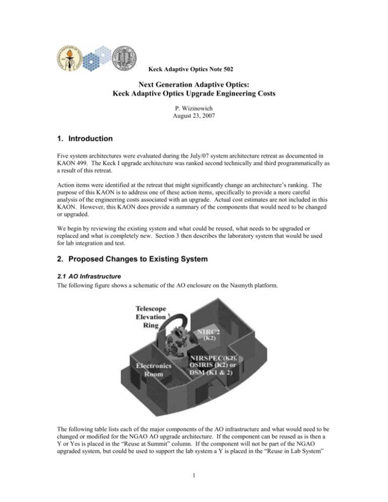
Keck Adaptive Optics Note 502 Next Generation Adaptive Optics: Keck Adaptive Optics Upgrade Engineering Costs P. Wizinowich August 23, 2007 1. Introduction Five system architectures were evaluated during the July/07 system architecture retreat as documented in KAON 499. The Keck I upgrade architecture was ranked second technically and third programmatically as a result of this retreat. Action items were identified at the retreat that might significantly change an architecture’s ranking. The purpose of this KAON is to address one of these action items, specifically to provide a more careful analysis of the engineering costs associated with an upgrade. Actual cost estimates are not included in this KAON. However, this KAON does provide a summary of the components that would need to be changed or upgraded. We begin by reviewing the existing system and what could be reused, what needs to be upgraded or replaced and what is completely new. Section 3 then describes the laboratory system that would be used for lab integration and test. 2. Proposed Changes to Existing System 2.1 AO Infrastructure The following figure shows a schematic of the AO enclosure on the Nasmyth platform. The following table lists each of the major components of the AO infrastructure and what would need to be changed or modified for the NGAO AO upgrade architecture. If the component can be reused as is then a Y or Yes is placed in the “Reuse at Summit” column. If the component will not be part of the NGAO upgraded system, but could be used to support the lab system a Y is placed in the “Reuse in Lab System” 1 column. If the component requires an upgrade to support the NGAO system a Y is placed in the “Upgrade” column. Finally if this is a new feature for NGAO or the component needs to be completely replaced this is indicated by a Y in the “New” column. An assumption is that DNIRI would go at the NIRC2 location and the near-IR and visible science instruments would move in on rails to the NIRSPEC/OSIRIS/DSM location. The near-IR and visible science instruments might need to be offset somewhat from the AO bench to allow room for a cascaded relay. Item Enclosure Enclosure extension into El ring Enclosure removal floor panels Electrical distribution Glycol distribution CCR distribution Lighting Ventilation system for personnel HEPA filters Electronics room heat exchanger Personnel entry ante-room AO bench room heat exchanger NIRC2 location defining pts SHARC, NIRC2 or OSIRIS Instrument exchange rails Instrument exchange defining pts Instrument interface panels Dual star module AO bench AO bench roof AO bench covers AO bench HEPA filter Window to enclosure AO bench room thermal control AO bench room humidity control DM electronics rack RTC electronics rack Motion control rack Communications rack Laser rack Interferometer rack Cable routing trays Cabling from electronics to AO bench Reuse at Summit Y = Yes Reuse in Lab System Upgrade New Y Y Y Y Y Y Y Y Y Y Not needed? For DNIRI Y (initially) Y Y Y Y Y Y Y (SHARC) If necessary If necessary Y (for easier access) Y Y Y Y Y Y Y Y Y Y Y Y Y Y Y Y Y As can be seen from the above table a great deal of the existing AO infrastructure can be reused. The new features have to do with cooling the AO enclosure, and with replacing the five AO electronics racks. The removed racks could be upgraded as appropriate to be used with the lab system. Note that parts of the AO infrastructure, especially the enclosure could potentially also be used with other NGAO architectures. 2 In terms of costs all (or most) of the above features will need to be provided for the other architectures. The extent to which they can be reused represents a cost savings. This reuse also represents a savings in terms of AO downtime, since the existing AO system and infrastructure would need to be removed before installation of a new system and its infrastructure. Any modifications to the telescope itself required for a new system, including such things as modifications to the platform or pulling new cables will require restrictions on the daytime use of the telescope. Utilization of the existing infrastructure discussed in this section. 2.2 AO Bench The following figure shows all of the current hardware on the AO bench. The following table lists each of the components indicated in the figure and what changes are recommended to be made for the NGAO upgrade architecture. Item 1. Image rotator 2. Tip/Tilt mirror 2. Tip/Tilt mount 3. OAP1 3. OAP mount 4. DM 5. DSM dichroic fold 5. DSM stage 6. OAP2 6. OAP mount 7. IR dichroic Reuse at Summit Yes Reuse in Lab System Option exists if new rot built Y Y Y Upgrade New With new 1st mirror Option exists to build 3rd rot Y Y Y Y Y Y Y Y Y Y Y Y Y 3 8. IR dichroic mount 9. OSIRIS fold mirror 9. OSIRIS fold mirror stage 10. Science fold mirror 10. Science fold mirror stage 11. IR ADC & stages 12. Vis ADC (not implemented) 13. Dichroic/beamsplitter changer & stage 14. Field steering mirrors 15. Wavefront sensor optics 16. Wavefront sensor camera 17. Intermediate fold mirror 18. Acquisition fold mirror 19. LBWFS 20. STRAP 21. Acquisition camera 22. Simulator fiber positioner 23. Telescope simulator 24. Wyko fold mirrors 25,26. DSM field separator 27. Boresite retroreflector 28,29. Accelerometers 30-34. NIRSPEC reimaging optics (only on K2) Wyko LOWFSs (new) LGS WFSs (new) Cascaded relay (new) Software: Optics bench/motion control Software: UI & Ops Tools Software: Supervisory Control Software: Real-Time Y Y Y Y Y Y Y Possibility Possibility Possibility Possibility Y (if CCID56) Y Y Possibility Possibility Y (to MAGIQ) Possibility Possibility Y Y Y Possibility Y Y Y Y Y Y Y Y Y Y Y As can be seen from the above table many of the existing components can be reused and some, like the tip/tilt mount, should be replaced. The new features would be required for any of the NGAO architectures. A number of the replaced components could be reused in the lab system subsequent to the telescope install of their replacements. 3. Laboratory System to Support Lab I&T An upgraded AO system requires a lab system, which would not be required for a new system, on which to test the upgrades. During and after NGAO implementation of any architecture there would be significant benefits to having an identical, or very similar, lab development system to support debugging initially and further development longer term. The following table lists the elements of a lab system that would support lab I&T of an AO upgrade to NGAO. The first column lists the components of the initial lab system. Most of this system would move to the telescope as described in KAON 500. Many of the components from the existing AO system could then be used in the lab system. The final lab system that would be used for ongoing developing and operational support is detailed in the second column of the table. The final column lists the components in the lab system that could be used as spares for the operational system. Lab System (initial) Lab System (final) 4 Spares in Final Lab System Clean room (exists) Bench Options: two non-custom 4x8’ benches or custom bench Telescope Simulator 1 (new) Fold from Simulator (new) Rotator options: nothing, folds or build a 3rd image rotator Tip/tilt mirror & stage (new) 2x OAPs (new) DM + electronics (new) Dichroics & changers (new) Acquisition camera/stage (new) LGS WFSs (new) NGS WFS (new) LOWFS (new) LBWFS (new) Real-time ctrl system 1 (new) Motion control rack (old/new) Motion control cables (new) Communications rack (new) Supervisory ctrl system (old/new) User tools (old/new) Wyko (lab unit) SHARC (old) NIR camera (new) Cascade + Vis camera DNIRI Same Same Telescope Simulator 2 (new) Same Same or summit image rotator Telescope Simulator 2 Tip/tilt mirror & stage (summit) 2x OAPs (summit) DM + electronics (summit) Dichroic (summit) Acquisition cam/stage (summit) LGS WFSs (spare units) NGS WFS (spare) LOWFS (spare) LBWFS (old upgraded) Real-time ctrl system 2 (new) Motion ctrl rack (summit/new) Same, but reduced number Comms rack (summit) Supervis ctrl sys (summit/same) Same Wyko (lab unit) SHARC (old) T/T mirror OAPs DM as temporary solution Dichroic as temporary solution Acq cam/stage Spare LGS WFSs Spare NGS WFS Spare LOWFS Image rotator if 3rd unit built RTC 2 Motion control hardware Cables Comms rack hardware Note that the costs of a long-term lab development system have not been included in the costs of any of the NGAO architectures. The upgrade path allows for the cheapest lab system since it reuses components from the existing AO system. However, the extent to which these reused components are not the same as the summit system will reduce the value of the lab system. These costs are minimized by utilizing similar approaches to those used in the current system, for example in adopting the same motion control architecture. 4. Conclusion This KAON has attempted to partially address the engineering costs concerns with the Keck AO upgrade architecture raised at the July/07 system architecture meeting. It does so by listing the components that would be reused, upgraded or replaced. This description can be used as a basis for generating cost estimates. The choices made in this document were intentionally made to minimize costs while still allowing the achievement of most of the NGAO requirements. Clearly NGAO operations would benefit if more of the components were upgraded both for maintenance and performance reasons. References Dekany, R. et al., NGAO System Architecture Definition, KAON 499 (July, 2007). Wizinowich, P., NGAO Keck AO Upgrade Programmatic Feasibility (Aug, 2007). 5


