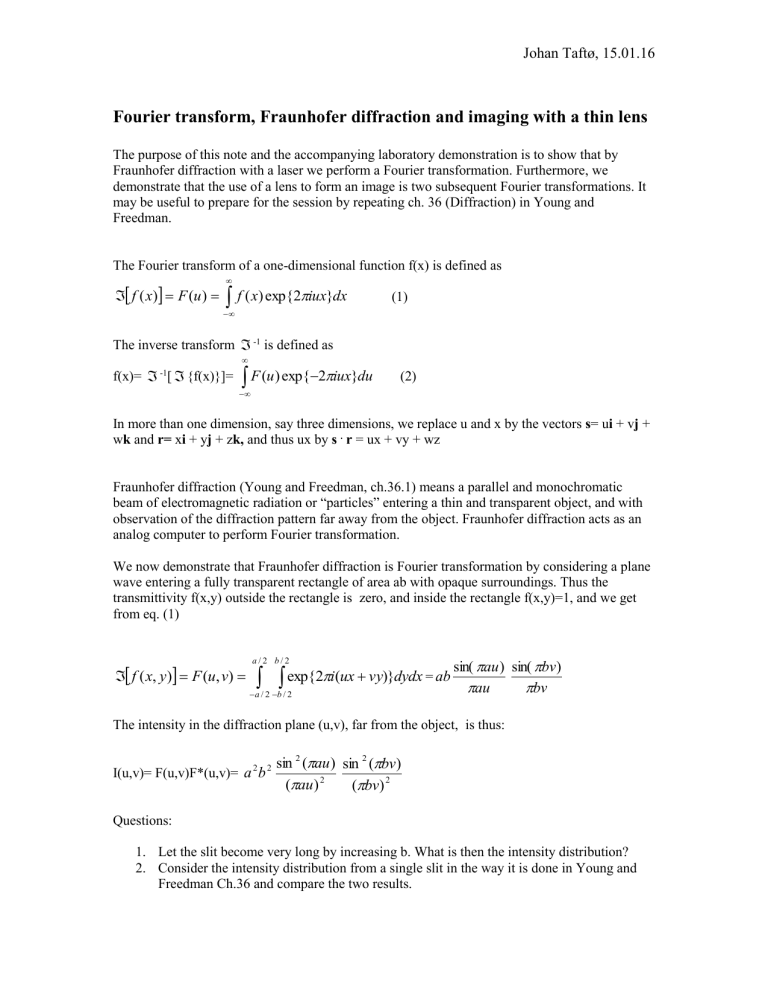
The Fourier transform of a one-dimensional function f(x) is defined as
Johan Taftø, 15.01.16
Fourier transform, Fraunhofer diffraction and imaging with a thin lens
The purpose of this note and the accompanying laboratory demonstration is to show that by
Fraunhofer diffraction with a laser we perform a Fourier transformation. Furthermore, we demonstrate that the use of a lens to form an image is two subsequent Fourier transformations. It may be useful to prepare for the session by repeating ch. 36 (Diffraction) in Young and
Freedman.
The Fourier transform of a one-dimensional function f(x) is defined as
f ( x )
F ( u )
f ( x ) exp{ 2
iux } dx (1)
The inverse transform f(x)=
-1 [
{f(x)}]=
-1 is defined as
F ( u ) exp{
2
iux } du (2)
In more than one dimension, say three dimensions, we replace u and x by the vectors s = u i + v j + w k and r= x i + y j + z k, and thus ux by s .
r = ux + vy + wz
Fraunhofer diffraction (Young and Freedman, ch.36.1) means a parallel and monochromatic beam of electromagnetic radiation or “particles” entering a thin and transparent object, and with observation of the diffraction pattern far away from the object. Fraunhofer diffraction acts as an analog computer to perform Fourier transformation.
We now demonstrate that Fraunhofer diffraction is Fourier transformation by considering a plane wave entering a fully transparent rectangle of area ab with opaque surroundings. Thus the transmittivity f(x,y) outside the rectangle is zero, and inside the rectangle f(x,y)=1, and we get from eq. (1)
f ( x , y )
F ( u , v )
a a
2 /
/ 2 b
b
/
/
2 exp{ 2
i
2
( ux
vy )} dydx = ab sin(
au au
) sin(
bv )
bv
The intensity in the diffraction plane (u,v), far from the object, is thus:
I(u,v)= F(u,v)F*(u,v)= a
2 b
2 sin
2
(
au )
(
au )
2 sin
2
(
bv )
(
bv )
2
Questions:
1.
Let the slit become very long by increasing b. What is then the intensity distribution?
2.
Consider the intensity distribution from a single slit in the way it is done in Young and
Freedman Ch.36 and compare the two results.
The thin lens
Among the radiation (x-ray, neutron and electron) commonly used to resolve interatomic distances, electrons are unique because electron lenses and electron microscopes are available.
Thus, the object can be studied in direct as well as reciprocal space. The electron microscope can be considered an analogue to visible light microscope at a much higher spatial resolution.
Object
f( r )
Back focal
plane
F( s ) =
[f( r )]
Image f( r )=
1
[F( s )]
=
1
{
[f( r )]}
Let us consider the figure above. In the back focal plane we have a Fraunhofer diffraction pattern of the object. We convince ourselves that so is the case by bearing in mind that parallel beams are focused in the back focal plane.
Assume a perfect lens, implying a one-to-one mapping of information between the object and the image. Thus, an inverse Fourier transform of the diffraction pattern is performed between the back focal plane and the image plane.
An aperture is commonly placed in the back focal plane so that only part of the diffraction pattern contributes to the image. Bright-field imaging is achieved when the aperture lets through only the beam in the forward direction (direct beam). In dark-field imaging the direct beam is excluded.
By placing a convex lens (projector lens) to the right of the image plane shown in the figure, we may image further to the right the image formed by first lens, objective, on a viewing screen. The image formed by the objective now acts as the object for the projector lens. In light microscopy, by moving the projector lens, we may image the back focal plane of the objective lens instead of its image plane on the viewing screen. In transmission electron microscopy we change the focal length of a projector lens in order to switch from image to diffraction pattern on the stationary viewing screen.
Proof of Babinet´s principle based on Fourier transform
Babinet´s principle says that performing Fraunhofer diffraction on a positive and on a negative film results in the same diffraction pattern except in the forward direction ( i. e. the center of the diffraction pattern).
Let us consider two two-dimensional objects with complementary transmittivities, a positive, P, with transmittivity T(x,y), and a negative, N, with transmittivity (1-T(x ,y)). The amplitude of the
Fraunhofer diffraction pattern for the positive, i. e. the Fourier transform now becomes:
P
( u , v )
T ( x , y ) exp{ 2
i ( ux
vy )} dx dy
Similarly for the negative:
N
( u , v )
( 1
T ( x , y )) exp{ 2
i ( ux
vy )} dx dy
The intensity now becomes:
I
P
( u , v )
P
( u , v )
P
( u , v )
( u , v )
P
( u , v ) and:
I
N
( u , v )
N
( u , v )
N
( u , v )
( u , v )
I
P
( u , v )
Thus, complementary two-dimensional objects result in equal intensity in the Fraunhofer diffraction pattern except at the origin. This is Babinet´s principle .
*Note that the delta function when u
0 and
has the value zero for all combinations of u and v except v
0 .
Then its value is 1.
