Uplink Power Control Simulation Assumptions
advertisement
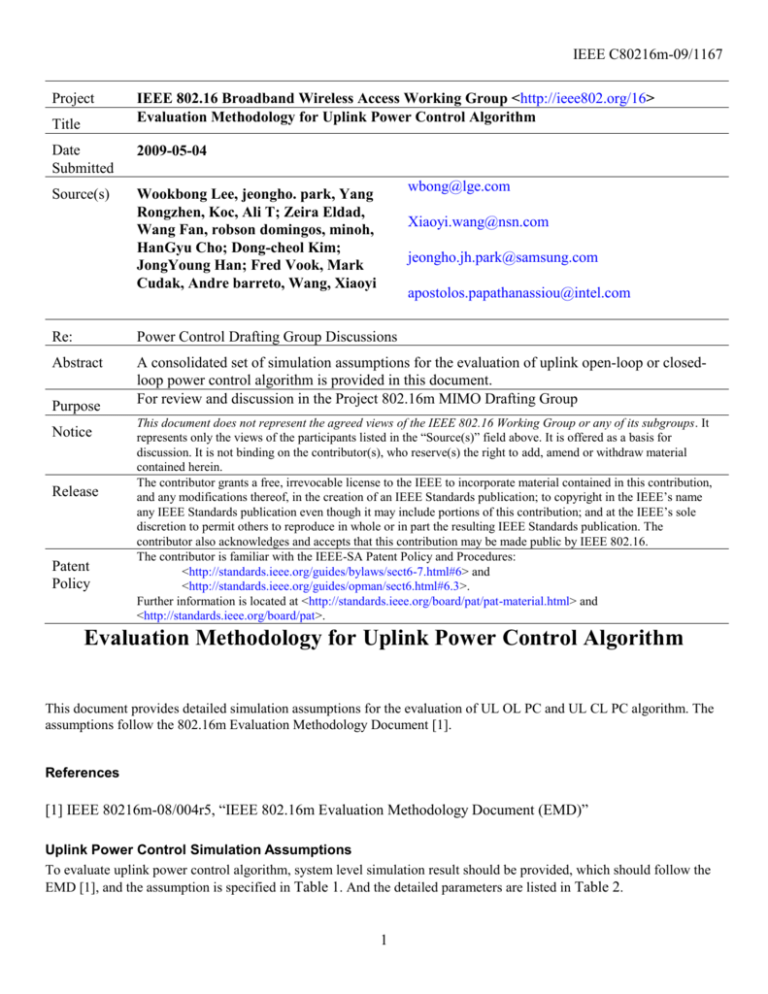
IEEE C80216m-09/1167 Project Title IEEE 802.16 Broadband Wireless Access Working Group <http://ieee802.org/16> Evaluation Methodology for Uplink Power Control Algorithm Date Submitted 2009-05-04 Source(s) Wookbong Lee, jeongho. park, Yang Rongzhen, Koc, Ali T; Zeira Eldad, Wang Fan, robson domingos, minoh, HanGyu Cho; Dong-cheol Kim; JongYoung Han; Fred Vook, Mark Cudak, Andre barreto, Wang, Xiaoyi wbong@lge.com Xiaoyi.wang@nsn.com jeongho.jh.park@samsung.com apostolos.papathanassiou@intel.com Re: Power Control Drafting Group Discussions Abstract A consolidated set of simulation assumptions for the evaluation of uplink open-loop or closedloop power control algorithm is provided in this document. For review and discussion in the Project 802.16m MIMO Drafting Group Purpose Notice Release Patent Policy This document does not represent the agreed views of the IEEE 802.16 Working Group or any of its subgroups. It represents only the views of the participants listed in the “Source(s)” field above. It is offered as a basis for discussion. It is not binding on the contributor(s), who reserve(s) the right to add, amend or withdraw material contained herein. The contributor grants a free, irrevocable license to the IEEE to incorporate material contained in this contribution, and any modifications thereof, in the creation of an IEEE Standards publication; to copyright in the IEEE’s name any IEEE Standards publication even though it may include portions of this contribution; and at the IEEE’s sole discretion to permit others to reproduce in whole or in part the resulting IEEE Standards publication. The contributor also acknowledges and accepts that this contribution may be made public by IEEE 802.16. The contributor is familiar with the IEEE-SA Patent Policy and Procedures: <http://standards.ieee.org/guides/bylaws/sect6-7.html#6> and <http://standards.ieee.org/guides/opman/sect6.html#6.3>. Further information is located at <http://standards.ieee.org/board/pat/pat-material.html> and <http://standards.ieee.org/board/pat>. Evaluation Methodology for Uplink Power Control Algorithm This document provides detailed simulation assumptions for the evaluation of UL OL PC and UL CL PC algorithm. The assumptions follow the 802.16m Evaluation Methodology Document [1]. References [1] IEEE 80216m-08/004r5, “IEEE 802.16m Evaluation Methodology Document (EMD)” Uplink Power Control Simulation Assumptions To evaluate uplink power control algorithm, system level simulation result should be provided, which should follow the EMD [1], and the assumption is specified in Table 1. And the detailed parameters are listed in Table 2. 1 IEEE C80216m-09/1167 Table 1 Assumption for uplink power control evaluation. Assumption Proposed uplink power control for evaluation Antenna configuration MIMO Scheme Channel Model Channel correlation Scenario Cellular Layout Notes Cf proposals Single transmit antenna at MS Two receive antenna with 4 lambda spacing uniform linear array at BS SIMO (mandatory) CSM (optional) Modified Ped-B 3km/h (mandatory) Mix Channel model, follow EMD definition (optional) Uncorrelated Channel : Zero Correlation Hexagonal grid, 19 cell sites, wrap-around, 3 sectors per site Distance-dependent path loss L=130.19 + 37.6log10(.R), R in kilometers Inter site distance/Penetration 1.5km/10dB (optional) for Mix Channel Model 0.5km/20dB (mandatory) for Ped-B 3km/h loss Shadowing standard deviation 8 dB Antenna pattern (horizontal) 2 , Am A min 12 3dB (For 3-sector cell sites with 3dB = 70 degrees, Am = 20 dB fixed antenna patterns) Users per sector Scheduling Criterion Mean IoT [TBD] 10 (EMD) Proportional Fair (PF for all the scheduled users) Less than [10] dB [TBD] Table 2 SLS parameters Parameter Assumption OFDM parameters 10 MHz (1024 subcarriers) OFDM symbols per subframe 6 Total number of UL subframe 3 Overhead Permutation Pilot OH (11.1% for SIMO, 22.2% for CSM) No control OH at this moment Distributed: IEEE 802.16m DRU in full bandwidth (mandatory) Localized: IEEE 802.16m Subband CRU (optional) 2 IEEE C80216m-09/1167 Number of total LRU in one subframe Channel State Information 48 Delay 1 frame (5ms) QPSK 1/2 with repetition 1/2/4/6, QPSK 3/4, 16QAM 1/2, 16QAM 3/4, Link Adaptation 64QAM 1/2, 64QAM 2/3, 64QAM 3/4, 64QAM 5/6 Chase combining, non-adaptive, synchronous. HARQ with maximum 4 retransmissions, 3 subframes ACK/NACK delay, no error on ACK/NACK. HARQ retransmission shall occur no earlier than the eighth subframe after the HARQ previous transmission. Proponents should provide details about their own implementation of CSM scheduling in HARQ retransmissions. No control overhead, latency timescale 1.5s, Scheduling 8 LRUs per each MS MIMO receiver Linear Minimum Mean Squared Error (LMMSE) PHY Abstract RBIR Data Channel Estimation Perfect data channel estimation Feedback Channel Measurement Perfect feedback channel measurement Mobile Max Power 23dBm Full bandwidth using FR=1 (Mandatory) FFR 4 FPs (optional) Scheduling periodicity Frame Appendix A: Details of IoT measurement (informative) IoTAvg is calculated per each frequency partition over frame or subframe. IoTAvg 1 N sym N N N sym in,l wn,l n 1 l 1 wn,l Where in,l is the total interference power summation at n-th subcarrier and l-th symbol. wn,l is white noise power And N is the number of subcarriers for the given frequency partition and Nsym is the number of OFDMA symbol for data transmission. If scheduling periodicity is set to frame, then Nsym is 18 and if scheduling periodicity is set to subframe, then Nsym is 6. Note that pilot tone should be excluded if pilot boosting is adopted. - Appendix B: Details of Result Metric Sector throughput Cell edge throughput : 5%-tile user throughput Averaged IoT (averaged value among all sectors’ IoTavg) IoT CDF (sampling instant value for every frame, every frequency partition of every sector) User throughput CDF 3 IEEE C80216m-09/1167 - User TX power CDF Average VS Cell edge user throughput ---- X: Average thoughput Y: Cell edge user throughput 4


