w/ grit shield & turbo elbow
advertisement
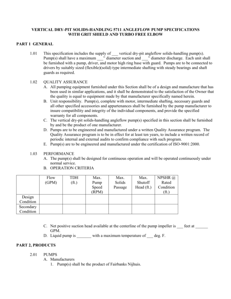
VERTICAL DRY-PIT SOLIDS-HANDLING 5711 ANGLEFLOW PUMP SPECIFICATIONS WITH GRIT SHIELD AND TURBO FREE ELBOW PART 1 GENERAL 1.01 This specification includes the supply of ___ vertical dry-pit angleflow solids-handling pump(s). Pump(s) shall have a maximum ___” diameter suction and ___” diameter discharge. Each unit shall be furnished with a pump, driver, and motor high ring base with guard. Pumps are to be connected to drivers by suitably sized (flexible)(solid) type intermediate shafting with steady bearings and shaft guards as required. 1.02 QUALITY ASSURANCE A. All pumping equipment furnished under this Section shall be of a design and manufacture that has been used in similar applications, and it shall be demonstrated to the satisfaction of the Owner that the quality is equal to equipment made by that manufacturer specifically named herein. B. Unit responsibility. Pump(s), complete with motor, intermediate shafting, necessary guards and all other specified accessories and appurtenances shall be furnished by the pump manufacturer to insure compatibility and integrity of the individual components, and provide the specified warranty for all components. C. The vertical dry-pit solids-handling angleflow pump(s) specified in this section shall be furnished by and be the product of one manufacturer. D. Pumps are to be engineered and manufactured under a written Quality Assurance program. The Quality Assurance program is to be in effect for at least ten years, to include a written record of periodic internal and external audits to confirm compliance with such program. E. Pump(s) are to be engineered and manufactured under the certification of ISO-9001:2000. 1.03 PERFORMANCE A. The pump(s) shall be designed for continuous operation and will be operated continuously under normal service. B. OPERATION CRITERIA Flow (GPM) TDH (ft.) Max. Pump Speed (RPM) Max. Solids Passage Max. Shutoff Head (ft.) NPSHR @ Rated Condition (ft.) Design Condition Secondary Condition C. Net positive suction head available at the centerline of the pump impeller is ___ feet at ______ GPM. D. Liquid pump is _______ with a maximum temperature of ___ deg. F. PART 2, PRODUCTS 2.01 PUMPS A. Manufacturers 1. Pump(s) shall be the product of Fairbanks Nijhuis. 2. Manufacturer shall have installations of like or similar application with a minimum of 5 years service for this pump size. B. Design 1. Rotation a. The pump will be (clockwise)(counterclockwise) rotation when viewed from the driver end looking at the pump. 2. Impeller a. The impeller shall of close-grained cast iron conforming to ASTM A48 CL30 and be of the ___-vane, enclosed mixed-flow design, single suction, solids-handling type designed to pass a minimum sphere size of ____” diameter. b. The impeller is to be dynamically balanced and secured to the shaft by means of a key, and impeller capscrew, and matched to the volute/casing. The arrangement shall be such that the impeller cannot be loosened from torque in either forward or reverse rotation. c. Wiper vanes on the back impeller shroud are not allowed. 3. Volute/Casing a. The volute shall be matched to the impeller and made of close-grained cast iron conforming to ASTM A48 CL30. The volute is to be of one-piece design (split volute on 42” and larger) with smooth fluid passages large enough to pass any size solid that can pass through the impeller. b. The volute shall be side flanged tangential discharge and capable of rotation in 45 degree increments to accommodate piping orientation. The volute shall be designed to permit front or back impeller removal. Diffusion vanes are not permitted. c. The volute shall be furnished with a large contoured inspection and cleanout opening located at the cutwater, to allow access to the impeller. Discharge flange 125 lb. ANSI drilling. d. The volute shall be designed to permit front or back impeller removal and to permit the removal of the rotating assembly without disturbing the suction or discharge piping. The casing shall be hydrostatically tested to 1.5 times the design head or 1.25 times the shutoff head whichever is greater. 4. Wear Ring and Grit Shield a. Axial-type removable wear ring is to be provided on the impeller for reduction of recirculation. b. Wear ring shall be stainless steel. c. Volute shall be fitted with a renewable grit shield to prevent erosion of the volute. The grit shield shall be of heat treated 550 – 650 Brinell 25% chrome iron. The grit shield shall incorporate intermediate raised sections to break up the rotational patterns of the pumpage. 5. Fronthead a. The fronthead shall be made of close-grained cast iron conforming to ASTM A48 CL30 and have the base integrally cast (42” & larger has separate fabricated base). It shall be cast separately of the volute. Fronthead suction flange shall be 125 lb. ANSI drilling. b. Fronthead shall incorporate a hand hole for inspection. 6. Suction Elbow a. A suction elbow shall be provided and be of a low height profile type. This low profile suction elbow shall have the flow characteristics equal to or greater than that of a long radius elbow so as to produce a smooth laminar flow to the impeller eye. b. Suction elbow shall be provided with a hand hole for inspection. 7. Backhead a. A separately cast close-grained cast iron backhead with large access openings and integral sealing box conforming to ASTM A48 CL30 shall be provided. The sealing box shall be 8. 9. 10. 11. 12. cast integrally with the backhead and be designed to accommodate either packing or mechanical seal without re-machining. The sealing box shall be drilled and tapped for external flushing with seal cage. b. A ¾” minimum backhead drain tap shall be provided. Sealing box leakage will be collected by the backhead drain trough and piped directly to drain, eliminating any drippage to the floor. c. A minimum of ___ rings of graphite-impregnated synthetic packing and a split Teflon water seal ring shall be furnished. Glands shall be two-piece split interlocking, made of cast iron (bronze), held in place by studs and nuts. Bearing Frame Assembly a. The bearing housing shall be close-grained cast iron conforming to ASTM A48 CL30 and of heavy, rugged design for carrying the bearings and machined for accurate and permanent bearing alignment completely enclosing the shaft between the bearings. Bearing supports are to be of heavy-duty construction providing for self-centering fit with the casing for proper alignment. The bearing housing shall be of dust-proof design, incorporating lip-type grease seals in contact with the shaft to prevent the entrance of contaminants. Jacking bolts for external impeller adjustments are required (8” and 18” and larger do not use jacking bolts). Zerk-type grease fittings for bearing lubrication shall be supplied at the bearing housing. b. The pump shaft shall be made from type 4140 alloy steel, of sufficient diameter to carry the maximum loads imposed and to prevent vibration and fatigue. The shaft shall be accurately machined along its entire length. Keyways shall be provided at both ends. c. A renewable shaft sleeve, positive adhesive sealed to prevent leakage between the shaft and the sleeve, shall protect the shaft through the sealing box area. The shaft sleeve shall be stainless steel with Brinell hardness of 300-350. d. Radial (inboard) bearings shall be grease-lubricated single-row deep-grooved ball type (double-row on 14” & 16”)(spherical roller on 18” thru 54”), self-aligning, designed to carry the hydraulic radial loads encountered in the service conditions. Thrust (outboard) bearings shall be angular contact, duplex mounted (tapered roller on 18” thru 54”), designed to carry the pump hydraulic axial and dead load thrust. e. Bearings shall be designed for an L10 life of 100,000 hours per AFBMA at best efficiency point. Grease relief ports with plugs shall be provided. Fits and Hardware a. The volute/casing, fronthead, backhead, and frame shall be manufactured with concentric shoulder fits to assure accurate alignment. All machined bolts, nuts, and capscrews shall be of the hex-head type and will not require the use of any special tools. High Ring Base a. The motor high ring base shall be cast iron or fabricated steel of adequate height to permit access to the coupling and furnished with a shaft guard. Vibration Limitations (Field) a. The limits of vibration as set forth in the standards of the Hydraulic Institute shall govern. Testing a. A certified factory hydrostatic and performance test shall be performed on each pumping unit in accordance with Hydraulic Institute Standards, latest edition. Tests shall be sufficient to determine the curves of head, input horsepower, and efficiency relative to capacity from shutoff to 150% of design flow. A minimum of six points, including shutoff, shall be taken for each test. At least one point of the six shall be taken as near as possible to each specified condition. b. Results of the performance tests shall be certified by a Registered Professional Engineer and submitted for approval before final shipment. 13. Pumps shall be manufactured by companies whose management system is registered to ISO9001:2000
