Lab 10 help
advertisement
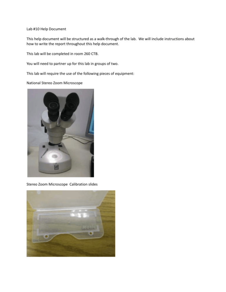
Lab #10 Help Document This help document will be structured as a walk-through of the lab. We will include instructions about how to write the report throughout this help document. This lab will be completed in room 260 CTB. You will need to partner up for this lab in groups of two. This lab will require the use of the following pieces of equipment: National Stereo Zoom Microscope Stereo Zoom Microscope Calibration slides Magnifying glasses Hybrid for pacemaker, ceramic substrate, PGA Hybrid, polyimide on metal substrate Large MCM, ceramic substrate, PGA, top view Small MCM, ceramic substrate, PGA MCM, sectioned at via Dial Calipers Procedure Observe each of the MCM or hybrid samples. Determine for each the number of IC chips (actual or sites for them), the number of chip resistors & capacitors (you do not need to try and tell the difference between them; just count them together), the number of thin or thick film resistors, and other devices. Take a picture of one of each of these different types of devices, and give its dimensions. DO NOT just use the images on the class website – those are simply to help you prepare for the lab. Seeing something in the microscope for yourself is a MUCH better learning experience than just looking at the pictures. Basically, you are performing the same series of steps for each of the above listed samples. Structure your lab report using the following layout or a similar one. We'll offer help and suggestions throughout. Note: You will only need the microscope for the sectioned MCM. The other boards and their components are large enough that you should be able to make your observations using the naked eye or a magnifying glass. You are still welcome to use the microscopes to observe the boards and we encourage you to do it so that you can see for yourself the detail of the components and their assembly on the substrates. Here is a list of the first 4 substrates: Hybrid for pacemaker, ceramic substrate, PGA Hybrid, polyimide on metal substrate Large MCM, ceramic substrate, PGA, top view Small MCM, ceramic substrate, PGA For each of these 4 substrates, perform the following steps Determine for each the number of IC chips (actual or sites for them)-The IC’s will usually be large square components with lots of circuit pathways going to and from them. The sites for IC’s will be either square or rectangular and will consist of circuit pathways that form the square or rectangular shape of the site. Not all chips (chip sites) are the same size despite being on the same substrate. Include the number of IC’s and/or IC sites in your lab report. Count the number of chip resistors & capacitors (you do not need to try and tell the difference between them; just count them together)-The chip resistors and capacitors will be those small, rectangular components on the substrate that have one circuit path in and out. These look similar to thin and thick film resistors that are present on these substrates, but the thin/thick film components are usually much larger than the chip components. Some substrates will only have pairs of what look like small, rectangular contact pads. Assume that these are for chip components and count each pair as if it were a chip component. All substrates should have some chip components or chip component contact pads on them. Include the number of chip components and/or chip component contact locations in your lab report. Count the number of thin or thick film resistors, and other devices-There are far fewer of these than chip components. They are usually larger than chip components. Not all of the substrates will have these. Include the number of thin/thick film components in your lab report. If there aren’t any on this substrate, say so. Take a picture of one of each of these different types of devices, and give its dimensions-This is pretty self-explanatory. The devices that it is referring to are the different components on the chip. Measure the size of one IC chip, one chip component (or component pad), and one thick film component (if any). Also, take a picture of each of the 4 substrate samples (whole MCM or hybrid) to include in that sample’s respective section in your lab report. Make sure the picture shows each of the devices on the substrate clearly. MCM, sectioned at via This component is a cross section of an MCM. You will need the microscope for this component. Instead of measuring the size of this substrate as you did with the other substrates, measure the thickness of it using either the calipers or the microscope Motic software. Record this measurement in your lab report. Since you can’t tell how many resistors or other components are actually on this MCM, observe it and note any features that could be resistors, circuit paths, or other components. Describe these features and what kind of component you think that they are in your lab report. Take a picture of the sectioned MCM and include that in your lab report. Equipment The only piece of equipment for the lab report that needs a manufacturer is the microscope. Say: National Stereo Zoom Microscope (these don’t seem to have serial numbers or model numbers on them so don’t worry about those.) List any other pieces of equipment that you used as well. Conclusion Compare your observations of these MCMs and hybrids to the IC packages; describe both the differences and similarities. Basically, you are comparing these substrate samples to the samples you looked at during the last lab. How are they similar and how are they different? Examples of things to consider: number of IC chips on MCM’s and hybrids vs. on IC packages, relative sizes of MCM’s and hybrids compared to IC packages, number of other components on MCM’s and hybrids compared to IC packaging.

