Photoelectric Effect
advertisement
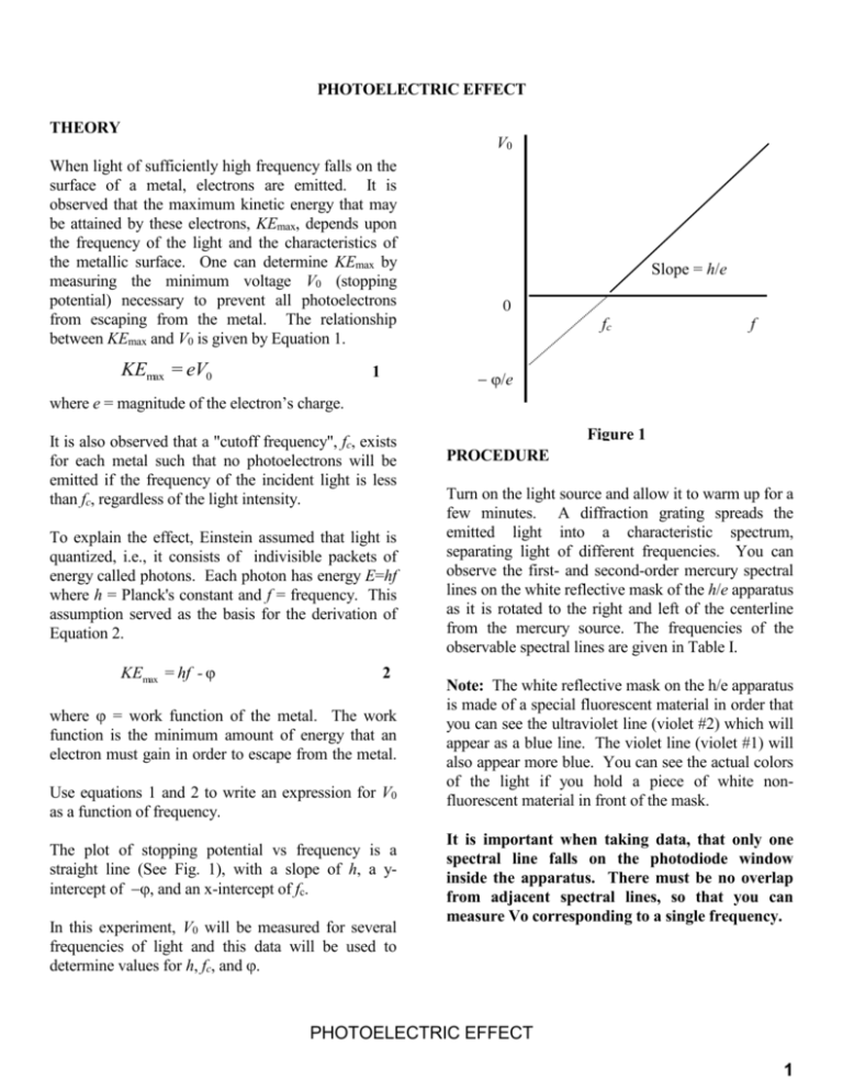
PHOTOELECTRIC EFFECT THEORY V0 When light of sufficiently high frequency falls on the surface of a metal, electrons are emitted. It is observed that the maximum kinetic energy that may be attained by these electrons, KEmax, depends upon the frequency of the light and the characteristics of the metallic surface. One can determine KEmax by measuring the minimum voltage V0 (stopping potential) necessary to prevent all photoelectrons from escaping from the metal. The relationship between KEmax and V0 is given by Equation 1. KEmax = eV0 1 Slope = h/e 0 fc f /e where e = magnitude of the electron’s charge. It is also observed that a "cutoff frequency", fc, exists for each metal such that no photoelectrons will be emitted if the frequency of the incident light is less than fc, regardless of the light intensity. To explain the effect, Einstein assumed that light is quantized, i.e., it consists of indivisible packets of energy called photons. Each photon has energy E=hf where h = Planck's constant and f = frequency. This assumption served as the basis for the derivation of Equation 2. KEmax = hf - φ 2 where = work function of the metal. The work function is the minimum amount of energy that an electron must gain in order to escape from the metal. Use equations 1 and 2 to write an expression for V0 as a function of frequency. The plot of stopping potential vs frequency is a straight line (See Fig. 1), with a slope of h, a yintercept of , and an x-intercept of fc. In this experiment, V0 will be measured for several frequencies of light and this data will be used to determine values for h, fc, and . Figure 1 PROCEDURE Turn on the light source and allow it to warm up for a few minutes. A diffraction grating spreads the emitted light into a characteristic spectrum, separating light of different frequencies. You can observe the first- and second-order mercury spectral lines on the white reflective mask of the h/e apparatus as it is rotated to the right and left of the centerline from the mercury source. The frequencies of the observable spectral lines are given in Table I. Note: The white reflective mask on the h/e apparatus is made of a special fluorescent material in order that you can see the ultraviolet line (violet #2) which will appear as a blue line. The violet line (violet #1) will also appear more blue. You can see the actual colors of the light if you hold a piece of white nonfluorescent material in front of the mask. It is important when taking data, that only one spectral line falls on the photodiode window inside the apparatus. There must be no overlap from adjacent spectral lines, so that you can measure Vo corresponding to a single frequency. PHOTOELECTRIC EFFECT 1 Table I MERCURY SPECTRAL LINES Color Violet #2 Violet #1 Blue Green Yellow Frequency (Hz) 8.20 x 10¹⁴ 7.41 x 10¹⁴ 6.88 x 10¹⁴ 5.49 x 10¹⁴ 5.19 x 10¹⁴ bars. Be sure to scale your graph and extend your best-fit line, to clearly illustrate both the x- and yintercepts. Fit the graph to determine the values of h, , and fc, along with the error in each value. Compare your value of h to the standard value, and comment on whether your value is within measurement error of the standard. Now similarly measure the stopping potential for the five second-order spectral lines, once again getting six Vo values for each frequency. Determine the average stopping voltage Vave for each frequency, and determine the standard deviation of the mean m. Determine the stopping voltage, Vo, for each of the spectral lines listed in table I. To do this, rotate the apparatus around the light source and rotate the box on its stand until the line of interest is focused on the aperture inside the apparatus. Be sure that the light shield is closed whenever taking data, to prevent stray light of other frequencies from entering the window. Press the ZERO button on the side panel of the h/e apparatus (near the ON/OFF switch) to discharge any accumulated potential in the unit's electronics. Read the output voltage on the digital voltmeter. (The voltmeter should be on the lowest setting for which it is not overloaded.) Wait until the voltmeter has stabilized at a constant value before recording the voltage. Important: Use the appropriate filters when making measurements with the green and yellow spectral lines. Do this procedure for each of the five first-order spectral lines given in Table I, both on the right and on the left. Then repeat the measurement of these first-order-line stopping voltages two more times for each color on each side. Do not just leave the apparatus in place and take several measurements – the placement of the apparatus can lead to systematic error. You should have six values of Vo for each frequency. Is the error for the second-order values better or worse than for first-order? Based on your observation of the spectral lines, does this make sense? Explain. Create a new plot of Vave vs frequency, this time plotting two points for each frequency – the 1st-order value and the 2nd-order value – including error bars for each. Fit the graph to determine the values of h, , and fc, along with the error in each value. Did you get more accurate values for h, , and fc by including the less-accurate 2nd-order data? Does this make sense? Explain. Do you think that including extra data will always increase accuracy, even if the data is less accurate? It might help to make a graph of your good data along with fake data with ridiculously large error bars, and see what happens to the error in your fit values. Determine the average stopping voltage Vave for each frequency, and determine the standard deviation of the mean m. Plot Vave vs frequency, including error PHOTOELECTRIC EFFECT 2
