Lining a steep slope valley landfill – it must not leak!
advertisement
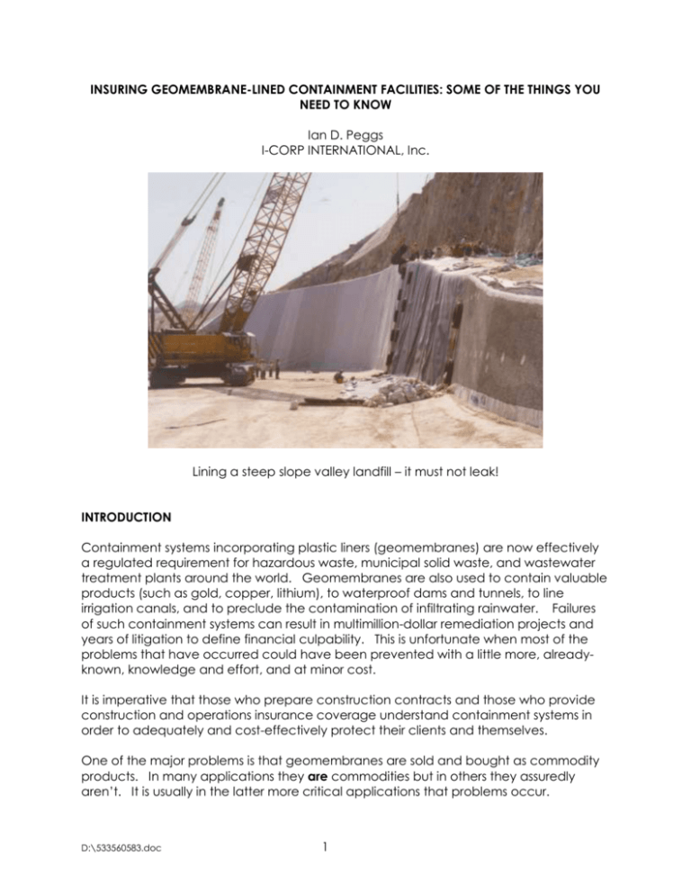
INSURING GEOMEMBRANE-LINED CONTAINMENT FACILITIES: SOME OF THE THINGS YOU NEED TO KNOW Ian D. Peggs I-CORP INTERNATIONAL, Inc. Lining a steep slope valley landfill – it must not leak! INTRODUCTION Containment systems incorporating plastic liners (geomembranes) are now effectively a regulated requirement for hazardous waste, municipal solid waste, and wastewater treatment plants around the world. Geomembranes are also used to contain valuable products (such as gold, copper, lithium), to waterproof dams and tunnels, to line irrigation canals, and to preclude the contamination of infiltrating rainwater. Failures of such containment systems can result in multimillion-dollar remediation projects and years of litigation to define financial culpability. This is unfortunate when most of the problems that have occurred could have been prevented with a little more, alreadyknown, knowledge and effort, and at minor cost. It is imperative that those who prepare construction contracts and those who provide construction and operations insurance coverage understand containment systems in order to adequately and cost-effectively protect their clients and themselves. One of the major problems is that geomembranes are sold and bought as commodity products. In many applications they are commodities but in others they assuredly aren’t. It is usually in the latter more critical applications that problems occur. D:\533560583.doc 1 In this paper we will outline some of the failures that have occurred and explain how some of the differences in only one aspect of geomembrane specification (surface modification – roughness, adhesion, impermeability, color) can be the difference between acceptable and problematic performance. The same principle applies to other aspects of lining systems and to all construction projects in general. GEOMEMBRANE CHARACTERISTICS Geomembranes are thin flexible sheets of plastic typically between 0.020 and 0.100 in. (0.5 to 2.5 mm) thick, 6 to 30 ft (2 to 10 m) wide, and 650 to 1750 ft (210 to 570 m) long. Smaller rigid sheets up to about 0.25 in. (6 mm) thick are used to line concrete tanks and basins. Rolls of geomembrane are conventionally welded together to cover very large areas (up to 250 acres [100 ha]) by thermal fusion, extrusion of a narrow molten bead of the same plastic over the edge of the top overlapping sheet, or by adhesion bonding. When properly done the fusion and extrusion seams cannot be peeled apart, while the conventional adhesively bonded seams generally can be peeled apart. However, provided the peeling force exceeds a specified value they are considered acceptable. This apparent dichotomy of standards has resulted in thermal fusion/extrusion fusion being the preferred welding method, although, as will be shown, new chemical surface-modification technology enables equally strong adhesive bonding. A book could be written on welding techniques, seam test methods, and seam specifications, but this is not the topic of this paper. There are many different materials from which geomembranes are made, but at present high density polyethylene (HDPE) is the predominant material – polyvinyl chloride (PVC), polypropylene (PP), and alloys of up to three or four polymers (plastics) are also available. Each has its own characteristic properties that make it more or less suitable than other materials in different applications, such that there is no longer a need to design an installation for a specific geomembrane material. HDPE has excellent general chemical resistance and high strength, but there are chemicals in which it will stress crack. It also has low deformation capabilities. It has a high expansion coefficient that causes it to expand and form waves in the sun, and pull tight (become stressed) at low temperatures. On the other hand PVC has a lower strength, but has high deformation capabilities, and does not stress crack. However, unlike HDPE, it must be covered to protect it against degradation (stiffening then cracking) by thermal exposure and ultraviolet radiation. PP has a combination of HDPE and PVC properties – it does not stress crack, it is tolerant of deformation, and can be left exposed to sunlight. It has half the expansion coefficient of HDPE and is much easier to weld. Clearly, there is not one geomembrane material that is applicable in all installations. HDPE would come close, but that way of thinking has become its Achilles’ heel. One associated difficulty is that HDPE geomembranes are made from many different HDPE resins with the consequence that the final products can vary by a factor of about 500 in D:\533560583.doc 2 their long-term mechanical durabilities. Hence, there is a need to distinguish between the commodity product, such as for a golf course pond, and the more critical product required to contain a hazardous waste liquid. The consequences of failure are very different in these two installations so should the same material installed to the same specifications be used in both? The liner for the latter should be far more durable. Liners are installed to prevent leakage. However, while clay liners may be expected to leak somewhat, geomembrane liners are generally held to a far higher standard and are not expected to leak at all. Despite this, it is United States Environmental Protection Agency policy to assume that all single geomembrane liners will leak to some small degree and that the lining system should be capable of handling such leakage, hence the requirement for a double lining system in hazardous waste facilities. The maximum allowable leakage rate through the primary (upper) liner is typically 20 gal/acre.day (200 l/ha.day). Both liners have the same number of flaws, but provided the leakage is removed from the secondary (lower) liner it will not have the constant liquid head on it that the primary (upper) liner does. While the primary liner might constantly “leak” the secondary liner does not leak at all. Therefore, the total lining system does not leak. This is the same principle for why the double-hulled ship does not sink - provided the space between the hulls is pumped. CASE HISTORY 1 – WASTEWATER TREATMENT PLANT A major international corporation lined a concrete basin in its wastewater treatment plant with a double liner of thick (too thick, too rigid) HDPE geomembrane. When filled, a few discrete drips persistently came out of the leakage collection system between the two liners. The contractor was called in to make repairs – the leak became worse. After a second call-back the leak was continuous. The corporation was not aware of the virtual impossibility of making a leak tight liner and requiring repairs only succeeded in making an acceptable installation unacceptable. How easy it would have been to recirculate a few drips back into the basin. The basin is about to be replaced with a large stainless steel tank. Now, who caused the problem? The design engineer for specifying a product that was more difficult to install than others? The installer for not installing a totally leak free liner? The owner for requiring that unnecessary repairs be made? Or even the regulator for making it easy to get a permit for HDPE when another less familiar material, but one that requires more deliberation, might have been more appropriate? It should not necessarily be assumed that if a Professional Engineer has stamped the drawings and the State has given a permit that a lining system will function as expected. And whose expectations are we to consider – do they understand geomembrane technology? SURFACE TREATMENTS As indicated, HDPE is considered the geomembrane material of choice at present, but there are many different HDPEs, just as there are many different automobiles – some perform better or more reliably than others. In addition, there are several different surface treatments both chemical and physical that can be given to HDPE D:\533560583.doc 3 geomembranes that will improve their performance in different circumstances. Not only will these treatments improve performance, they will allow HDPE to be used in circumstances in which a conventional “commodity” untreated HDPE geomembrane would fail. The most traditional of these surface treatments is a physical roughening (texturing) of the surface to provide more friction. Such geomembranes will not slide on steeper slopes, nor will the material on top of the geomembrane slip on the geomembrane. However the latter can be undesirable. CASE HISTORY 2 – LANDFILL BOTTOM LINER A new landfill cell had been constructed in the fall. On the side slopes the State required that the sand layer be increased in depth to provide better insulation of the clay under the double geomembrane during the cold winter. The lower geomembrane was textured on the bottom and smooth on top. The upper geomembrane was textured on both sides. Within a few days of adding the sand the slopes started moving downwards, all the upper layers sliding on the smooth top surface of the lower geomembrane Figure 1. It should have been clear that this might happen with the added weight of sand. Figure 1. Structure of lining system that pulled out of anchor trench and slipped on smooth top surface of secondary (bottom) liner. This event also identifies an advantage of having a geomembrane with a smooth top surface – material slides on it rather than sticking to it and tearing it so that it leaks. The liner can be used again. Alternatively, if sticking occurs but the induced stress is D:\533560583.doc 4 insufficient to cause the geomembrane to tear, the lower long-term stress may ultimately result in stress cracking – a brittle fracture at a constant stress lower than the short term break strength of the material - akin to a steady load fatigue failure. Who was responsible for this failure? The state for requiring the additional sand? The owner who might have added the sand without informing the engineer, or the engineer who allowed the sand to be placed? TEXTURED SURFACES Further, and to complicate the practical performance of friction enhancement by texturing, there are several methods of achieving a surface texture. As a result the nature of the roughened surface is quite variable (see Figure 2). In the most predominant method the surface is roughened during the primary geomembrane extrusion process to look like a rough ocean with variable high waves. With the specification of a minimum geomembrane thickness, it is required that more plastic is used to ensure that the lowest valley of the rough surface will not be lower than the minimum thickness. For equivalent thicknesses of rough and smooth materials the break strength and elongation properties of the textured product are lower than those for the smooth product. Thus the roughness compromises the strength of the material. Two other processes require the thermal bonding of a surface texture (short fine filaments or a powder) in a secondary process. In this case the minimum thickness of the geomembrane is well established (the thickness of the smooth sheet), however the durability of the surface texture bond is variable. It is a compromise between sufficient bonding to prevent the added texture from being scraped off (losing its purpose) and not overheating the bond to minimize the potential for local stress cracking over the long term. Thus, these two types of texture do not significantly affect the short-term break stress and elongation of the sheet as might be measured for quality control and quality assurance conformance testing. All three of these processes produce a random structure that is impossible to fully control both in terms of height of texture and distribution. A fourth method is calendering, in which the still warm and soft extruded sheet is rolled between profiled rollers that form a controlled reproducible pattern of cones, ridges, waves, or other raised features on the surface. In this process the minimum thickness of the sheet is well established, and the surface texturing is integral with the body of the sheet – it is not welded to the sheet. These textures are well-characterized. D:\533560583.doc 5 D:\533560583.doc 6 Figure 2. Textured geomembranes (previous page) – nitrogen (top), powder (middle), spray (bottom) calendered (above). For practical performance characteristics it is important to note that all of these profiles do not develop the same interface shear strength characteristics with all possible components of a lining system. The short filaments interact extremely well with the felttype geotextile cushions but not as well with subgrade clays. On the other hand, the cones and ridges of calendered products perform well with clays but not as well with geotextiles. Thus, it is very important to perform interface shear strength (friction) tests with the actual textured geomembrane proposed for the project against the actual site soils and adjacent geosynthetic layers. One of the more commonly-occurring failures is for cover soil to slide down the slopes on landfill caps (Figure 3) when the soil becomes saturated with rainwater because interface shear tests were performed in the laboratory with dry materials rather than with wet materials. D:\533560583.doc 7 Figure 3. Cover soil slippage on landfill cap WHITE SURFACES The second most traditional modified surface is a white surface which reflects sunlight better than black and results in the temperature of the liner being about 20oC cooler. However, one does need sunglasses to work on such a liner! Expansion and wrinkling during installation are minimized, better enabling the geomembrane to be placed flat against a clay subgrade and to achieve the 1000 times better impermeability that is designed to occur with an intimate contact composite lining system. If the geomembrane and clay are not in the specified 100% contact a defect in the geomembrane will not be effectively plugged by the adjacent clay, and water will be allowed to flow in the non-contact areas, thereby having a larger area of clay, and associated flaws, to flow through. If there are wrinkles in the liner that are folded over when the cover layers are placed on the liner, it is possible that the stresses generated by folding will ultimately cause the liner to crack and leak. A wrinkle or fold will also prevent leachate from a landfill draining away to the sump where it can be removed. Therefore, leachate will build up right at a location where the liner might crack. When bulldozers operate on the soil liner above a wrinkled geomembrane liner the possibility is increased that the bulldozer blade or tracks might catch on the top of a wrinkle and damage the liner, again at the location where leachate will collect – and leak. However, a white surface layer does not contain the same carbon black that provides the clear polyethylene resin with its excellent resistance to ultraviolet radiation. So while wrinkling problems are improved, UV resistance is compromised. Thus a white liner should not typically be left exposed. With another swing of the pendulum, the thin white layer makes it easy to see where the geomembrane has been damaged on the surface and the black bulk of the geomembrane has been exposed, as shown in D:\533560583.doc 8 Figure 4. Clearly, the pros and cons of any geomembrane material and any surface treatment need careful evaluation, again outlining the significant differences between commodity and specialty applications. Figure 4. Scratch and puncture damage easily visible on white surface. Scratch below and parallel to black scratch is not as deep. CASE HISTORY #3 – CAST-IN CONCRETE LINER Thick HDPE panels with studs on the back were cast into the concrete wall of a corrosive, valuable-liquid, containment facility. The gaps between the rigidly held panels were too wide to weld them together with a fillet extrusion bead so a loose cap strip was placed over the gap and welded on either side. In service the liquids were absorbed by the HDPE causing the cap to swell along the surface layer. The loose panel bowed outwards tending to lift and peel the edge welds off the rigidly held sheet on the wall, as shown schematically in Figure 5. The welds separated and started to leak. D:\533560583.doc 9 Figure 5. Schematic of liner swelling to cause seam separation (Fluoroseal) The installer was held accountable for making poor welds. However, the HDPE was clearly incompatible with the liquid otherwise absorption swelling would not have occurred. Normal geomembrane design philosophy is that the geomembrane shall not be stressed; it simply should act as a barrier. Normal geomembrane weld testing practice is that out of five test specimens cut from a weld sample only four must pass destructive testing – an allowed failure rate of 20%. This is only tolerated since seams are not expected to be stressed in service. However, in the concrete basin 100% of the welds were stressed, so it is not surprising that some failed – the 20% often expected to fail, unless more stringent specifications are imposed. Unfortunately, in this case, the absorbed liquids made it very difficult to make good repairs on the liner, since the owner did not want to shut the facility down in order to provide time for the absorbed liquids to evaporate. Who was responsible? The engineer for specifying a liner material that was incompatible with the liquids? The installer for poor workmanship or for average workmanship on a facility that would experience stresses he never expected? Or, the owner for not allowing time for adequate repairs? As investigations of this liner behavior were underway, stress cracking failures started to occur at wrinkles and locations of stress on a large section of liner that was not cast into the concrete. The liquid was oxidizing the surface of the HDPE and initiating cracks. The open cracks resulted in accelerated oxidation and accelerated cracking, the cracks finally penetrating the geomembrane. This was an extremely costly problem for all parties. D:\533560583.doc 10 SURFACE FLUORINATION This leads to the third and probably most interesting surface modification – a chemical fluorination treatment that allows HDPE to be used in liquid environments that would otherwise be absorbed in the surface layers, eventually to diffuse right through the HDPE. Gasoline will diffuse through conventional polyethylene and condense as a liquid on the far side – apparently “leaking”. However, several car manufacturer are able to use light, strong, HDPE gas tanks because the inside surface has been fluorinated, thereby providing a barrier to gasoline absorption and subsequent diffusion (see Figure 6). Such a treatment would probably have prevented the problems shown in Figure 5, and at minimal cost compared to the cost of the events that actually ensued – for all parties and their insurance companies. Figure 6. Schematic of surface fluorination (Fluoroseal) Testing by Sangam et al. (2001) on the resistance of fluorinated HDPE geomembranes in municipal sold waste landfills to typical benzene, toluene, ethyl benzene, and xylene concentrations in leachate show that the fluorination treatment decreases the permeability of these solvents through the liner by factors between 2.6 and 4.8. This is equivalent to increasing the thickness of the clay layer under the geomembrane from 2 ft (600 mm) to 5 ft (1.5 m). Thus the barrier performance of geomembranes to aggressive landfill liquids, and associated protection of groundwater, can be significantly improved by a simple surface treatment. However, not only does the fluorine surface treatment improve the barrier performance of the HDPE liner, the surface chemical treatment also enables it to be adhesively bonded to itself and to concrete and metal surfaces. In its untreated form HDPE geomembranes have very smooth surfaces to which almost nothing will stick for any length of time. In addition very low molecular weight components of the HDPE will rise to the surface effectively coating the surface with a waxy layer that makes adhesion very difficult. Even when HDPE geomembranes are thermally welded the waxes on the surface must be removed by grinding for extrusion welding, and are scraped off by D:\533560583.doc 11 the hot wedge during thermal fusion welding. Welding, particularly extrusion welding as is invariably used for repairs and detail work, requires specialized equipment with an experienced operator. Thus, making repairs can be costly and time-consuming if equipment and operators have to be brought in to remote sites for the simplest welding repair. Now, with fluorinated surfaces, a repair patch can be added by a local laborer using a two-part epoxy adhesive. The same epoxy adhesive can be used to bond HDPE geomembrane to concrete and steel over 100% of the contact area. In pull-off tests break occurs within the concrete rather than on the HDPE/concrete interface, as shown in Figure 7. Thus, the adhesive bond to the plastic is stronger than the adhesive itself. This provides superior sealing when compared to using mechanical batten strips and rubber gaskets where bolts are fasted on 6 in. or more centers and where leaks often occur at 90 degree corners where the strips are butted together and where bolts cannot be placed right at the ends, for maximum clamping effect. Not only does the adhesive make the bond, it also fills any roughness in the concrete surface thereby improving the quality of the seal. Figure 7. Peeled specimen; adhesive bond is stronger than concrete (Fluoroseal) Geomembranes can be welded to “lock strips” of the same plastic material cast into the edge of the concrete, but there can still be problems with eventual leakage along the plastic/concrete interface of the lock strip, and joints in the lock strip, particularly at corners, have to be carefully welded. And while the bonded width of an extruded bead might only be 0.5 or 0.75 in. on the top of the bottom sheet, the width of an adhesive bond could be several inches, thereby decreasing the possibility of the adhesive bond shearing apart. D:\533560583.doc 12 The adhesive bond can also be made underwater, which opens up many different technical opportunities and which necessitates a re-thinking of underwater liner construction and operating policies in major projects such as waterproofing the upstream faces of concrete dams which have cracked and are leaking. Increasingly, such dams are repaired with loose geomembranes mechanically fastened to the dam face with periodic vertical stainless steel channels. In a multiple liner welding process the channels are in turn covered by geomembrane and made waterproof. Then the liner is attached to the side and base of the dam face with stainless steel batten strips. Until recently, such repairs have required a complete draining of the reservoir, a very time-consuming and costly procedure. One prototype project has been performed by the US Army Corps of Engineers to line a dam face underwater, but again this is a very costly procedure requiring some precise drilling and fitting work under very difficult circumstances. And, since the liner is not fully bonded to the dam face, a geotextile or geonet drainage layer is required between liner and concrete to allow any leakage through the liner to be drained away and removed. If this leakage is not removed the liner is not effective. Thus it becomes important to test the installed liner for leakage before the reservoir is filled. Alternatively, the fluorination surface treatment allows the liner to be adhered directly to the face of the dam without any vertical channels and additional seams, and without the batten strip around the edges. It can also be installed without having to remove water from the reservoir. In fact the properties of the epoxy adhesive, when spread on the concrete face of the dam, cause water underneath the epoxy to be expelled away from the concrete surface, thus enabling 100% intimate coverage of the concrete. Cavities in the concrete are filled and protrusions are provided with circumferential filling resulting in more uniform support for the liner. And since there is no gap between the concrete and liner there is no need for additional layers to provide a drainage capability. If there is a pinhole in the liner water does not fill the space between the liner and dam, the water in the pinhole is plugged by the epoxy. Construction is easier, there are fewer potentially problematic procedures, and ultimate risks are lower. Such a system of 100% adhesion to concrete rather than the periodic attachment of the cast-in liner, and the ability to fully adhere a cap strip would have prevented many of the problems in Case History #3. In fact, with the larger, thinner geomembrane rolls, there would have been no requirement for welds between panels on the walls. On a more mundane, but still important level, is the ability to easily and effectively line concrete basins in wastewater treatment plants and hog, dairy, and cattle farms. Additional benefits of surface fluorination are added protection against oxidation and the initiation of stress cracking, probably the predominant failure mechanisms in exposed HDPE geomembranes. D:\533560583.doc 13 CONDUCTIVE SURFACE LAYERS The fourth surface treatment is done on the underside of a liner – the surface layer is made electrically conductive by the addition of a higher proportion of carbon black. This facilitates a final electrical test for pinholes in the liner just as the corrosion protection coating on a high-pressure gas transmission line is tested for pinholes, the potential site for aggressive corrosion to occur. An electric potential is applied between the conductive coating on the underside of the liner and a brass brush that is dragged over the surface of the liner. At a pinhole, where there is no resistance provided by the plastic layer, there is a spark discharge which can be seen, heard, and otherwise recorded. Thus holes through the liner, and even some thin spots, can be detected and repaired before liquid is placed on the liner and actual leakage occurs. This should provide insurance companies and contract attorneys a benchmark to show that construction has been satisfactorily performed. It will also provide a benchmark beyond which subsequent problems are likely covered under an operations policy rather than a construction policy. Actually, pinholes are rarely the problem in liners - the major problems are stone puncture holes and gashes caused by bulldozers and other mechanical equipment that are simply covered over. This too could be the subject of another paper. Such a conductive surface layer also helps in the performance of a “water-lance” type of leak survey where positively charged water is directed on to the liner surface such that when it penetrates a hole and contacts the negatively charged conductive layer current flows and can be recorded. Leaks can be pinpointed. Typically, the subgrade soil would be used as the negatively charged layer, but where there is a wrinkle in the liner and the liner is not in contact with the subgrade the water lance survey would be ineffective. Incorporating the conductive layer in the geomembrane obviates this problem – the liner and conductive layer are always in contact. CASE HISTORY #4 – VERY LARGE POND LINER The division between construction and operations phases in relation to insurance protection was demonstrated in a very large single liner pond facility that was felt to be leaking since the production process was not meeting its expected yields. Visual surveys were performed and locations of suspected leakage identified. The hard crystalline salt deposit on top of the liner was removed and identical linear “cuts” were found in the liner at all suspect locations. The owner suspected sabotage during the insured construction phase. There was no operational insurance. The owner naturally made the claim that damage occurred during construction. After an extensive very costly investigation it was concluded that the act of removing liner cover material to expose the liner damage was itself causing the damage noted, and that other problems in the pond, not related to the liner, were causing deficiencies in the process. In addition there were many features of the design and activities during the construction process that resulted in extensive damage to the lining system that was not covered by liquid but that would become leaks as the facility expanded according to the design. The investigation revealed that the insurance company had not had the D:\533560583.doc 14 design reviewed for its effectiveness and constructability, and had not required any monitoring of construction to confirm that what was required was properly done and that changes in design would not compromise the quality of the liner. The predominant cause of liner failures at present, as investigated by this author, is a lack of sufficient knowledge of liner materials performance by design engineers. Civil and geotechnical engineers, even electrical engineers, with insufficient work in their own fields are expanding into the perceived lucrative environmental protection field to work with these “simple sheets of plastic that conform to the shape of the ground, that are completely impermeable, and that just need heating and pressing together to make a waterproof joint” – the true commodity product as promoted by the geomembrane industry. It is not as simple as this. CASE HISTORY #5 – WASTEWATER TREATMENT PONDS An extreme example of inadequate engineering knowledge involves an engineering group working its first geosynthetic clay liner (GCL) at a water treatment plant where the maximum leakage rate allowed through the liner was 500 gallons per acre.day (see Figure 8). Figure 8. Wastewater treatment pond The engineer calculated the leakage rate given the liner specifications and the depth of water to be contained. The leakage rate was too high. He asked the D:\533560583.doc 15 manufacturer of the GCL if the calculations had been done correctly – the manufacturer said they had, and confirmed that the proposed liner would not work. The engineer found an earlier brochure from the manufacturer’s literature that had a lower permeability specification that would just allow the allowable leakage rate to be met. The engineer asked the manufacturer if they would guarantee the lower number – the manufacturer declined. The engineer asked the manufacturer for the lowest number they would guarantee. The manufacturer obliged but the number was still not low enough to provide an acceptable leakage rate. Then the engineer remembered that for half the year the groundwater level would be higher than the floor of the ponds, thereby reducing the head on the liner (technically this was not a proper assumption) and therefore reducing the driving force for leakage. The reduced hydraulic head just brought the leak rate into compliance with the regulations. The engineer proceeded with the construction of several ponds. A full-scale hydrotest, with the pond full to 11 ft, was required to demonstrate compliance with the regulations. When there was 7 ft of water in the ponds the water level could be raised no further - they were leaking faster than they could be filled! Clearly, said the engineer and owner, the installer had installed a defective lining system – the material was defective or the installation had damaged the liner – we will not pay. Subsequent investigation revealed the leakage rate calculations described above together with the fact that there were rocks in the cover soil up to 10 in. long when the GCL manufacturer’s guidelines required no stones larger than 1 in. in contact with the GCL. In addition there should be more than 80% fines in the soil – there was actually only 10%. As a result the liner was not uniformly confined between the two soil layers. Consequently, there were many abrasion and puncture holes in the GCL. The design engineer was finally held accountable and the ponds were lined with geomembranes, as should have been done in the first place. A contract between the owner and general contractor should never have been approved, nor should the engineer have been allowed to proceed with such a lining system. There was no effective peer review of the design performed for any of the project parties. And the review performed for the engineer was totally ignored. The project should not have been allowed to proceed. Nor should insurance coverage have been provided. CASE HISTORY #6 – LINER MANUFACTURING In a case of a different kind, a North American distributor/installer of a Europeanmanufactured HDPE cast-in concrete liner (CIL) thought it might be more economical to have the sheet produced in North America and to weld on the studs themselves. However, the European HDPE resin was not available in the USA. A full disclosure of the properties of the original resin, the method of welding on the studs, the product specifications required, service conditions of the sheet, and the mode of installation, were provided to potential manufacturers of the sheet. A manufacturer promising “equal or better” performance was selected to make sheet. Six months after their construction the first three installations failed catastrophically by stress cracking at every weld. Once again the installer was faulted for obvious improper welding. It was D:\533560583.doc 16 subsequently found that the resin used to make the sheet had an extremely low stress cracking resistance and that the added heat of welding was sufficient to initiate stress cracks that slowly (over 6 months) propagated through the sheet resulting in cracking and extensive leaking. Responsibility? The fabricator, working with HDPE should certainly have been aware of the need for good stress cracking resistance, the single most important performance parameter of HDPE products, but one that does not appear on conventional specification sheets. However, the sheet manufacturer, having been provided with all material specifications, installation procedures, and operating conditions, should have been far more knowledgeable of the requirement for good stress cracking resistance and the performance of its products. The costs to all parties, not only financial but also in reputation, was very high and all because a confirmatory test costing $250 was not performed. It is interesting to note that the sheet in this case history, although not having a conductive back surface, was electrically tested for leaks when installed – copper wires were installed behind the welds. Leaks were repaired, but the added heat of the repair process simply made the material even more susceptible to stress cracking! Had the same sheet been fluorinated it would have been possible to attach large panels to the walls without seams, to make joints with an epoxy adhesive therefore without heating, and the surface would not have been as susceptible to stress crack initiation. Typically, we continue to see that materials problems are initiated on surfaces and work their way inwards until ultimate failure occurs. Many times the agency that initiates the problem cannot be avoided since it is the thing we are trying to contain. Therefore, if the surface of the material can be beneficially modified to prevent the initiation of the problem and to optimize the performance of the containment system, it is worth doing. SUMMARY As geomembrane-based lining systems become more accepted by owners and regulators so too are the numbers of failures increasing. Approximately 60 % of failures are due to inadequate designs, 20% to poor installation, 10% to inferior materials, and 10% to miscellaneous items. Therefore, with a little extra knowledge of the performance characteristics of the different liner materials and a knowledge of the surface treatments that can be given to improve the applicability of the geomembrane material of choice (HDPE), a significant impact on 70% of presently occurring failures could be made. These treatments allow the safer use of HDPE geomembranes on slopes, they minimize expansion and contraction problems, they allow easier testing for the presence and location of leaks, and they allow the safer containment of organic liquids, the ability to fully bond HDPE with more security to concrete and steel structures and to itself, and the ability to bond to concrete and steel underwater. D:\533560583.doc 17 The insurance and legal (contract) professions can take the following simple steps to better assure the quality of any geomembrane containment installation and its longterm satisfactory performance: Require the review of all material specifications, project specifications, and project drawings, by an experienced independent engineer who is not likely to provide negative criticism for competition’s sake Require the review of candidate contractors to ensure they have a level of experience commensurate with the criticality of the project Consider the preparation of a documented construction quality assurance plan. Require experienced construction quality assurance monitors to be on site when the liner is being installed to ensure compliance with the project specifications and to ensure that workmanship is of adequate quality. The cost of such a proactive program is far less than the costs of dealing with a failure and an environmental disaster. REFERENCES Sangam, H.P., Rowe, R.K., Cadwallader, M.W., and Kastelic, J.R., “Effects of HDPE Geomembrane Fluorination on the Diffusive Migration of MSW Organic Contaminants”, Geosynthetics Conference 2001, IFAI, Roseville, MN, pp163-176. * * * D:\533560583.doc 18

