X-ray Diffraction: Analyzing Crystal Structures
advertisement
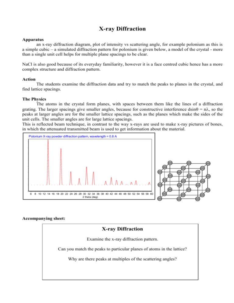
X-ray Diffraction Apparatus an x-ray diffraction diagram, plot of intensity vs scattering angle, for example polonium as this is a simple cubic – a simulated diffraction pattern for polonium is given below, a model of the crystal - more than a single unit cell helps for multiple plane spacings to be clear. NaCl is also good because of its everyday familiarity, however it is a face centred cubic hence has a more complex structure and diffraction pattern. Action The students examine the diffraction data and try to match the peaks to planes in the crystal, and find lattice spacings. The Physics The atoms in the crystal form planes, with spaces between them like the lines of a diffraction grating. The larger spacings give smaller angles, because for constructive interference dsin = n, so the peaks at larger angles are for the smaller lattice spacings, such as the planes which make the sides of the unit cells. The smaller angles are for large lattice spacings. This is reflected beam technique, in contrast to the way x-rays are used to make x-ray pictures of bones, in which the attenuated transmitted beam is used to get information about the material. Polonium X-ray powder diffraction pattern, wavelength = 0.8 A 6 8 10 12 14 16 18 20 22 24 26 28 30 32 34 36 38 40 42 44 46 48 50 52 54 56 58 60 2 theta (deg) Accompanying sheet: X-ray Diffraction Examine the x-ray diffraction pattern. Can you match the peaks to particular planes of atoms in the lattice? Why are there peaks at multiples of the scattering angles?


![NanoLab (Phys4970) X-ray Diffraction [ver 2.0] L.A. Bumm/M.B.](http://s2.studylib.net/store/data/018221141_1-18af304ed7aaf90c35852e5ba6391d73-300x300.png)
