DFD rules - University of Toronto Scarborough
advertisement
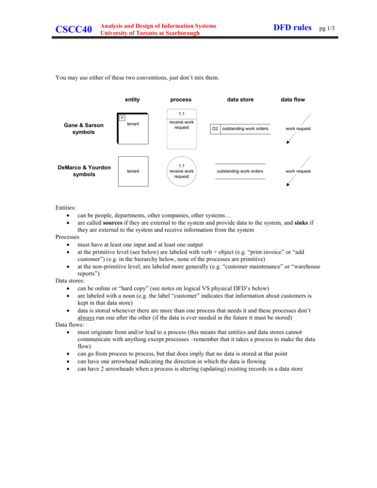
CSCC40 Analysis and Design of Information Systems University of Toronto at Scarborough DFD rules pg 1/3 You may use either of these two conventions, just don’t mix them. entity process data store data flow 1.1 id Gane & Sarson symbols DeMarco & Yourdon symbols tenant tenant receive work request 1.1 receive work request D2 outstanding work orders work request outstanding work orders work request Entities: can be people, departments, other companies, other systems… are called sources if they are external to the system and provide data to the system, and sinks if they are external to the system and receive information from the system Processes must have at least one input and at least one output at the primitive level (see below) are labeled with verb + object (e.g. “print invoice” or “add customer”) (e.g. in the hierarchy below, none of the processes are primitive) at the non-primitive level, are labeled more generally (e.g. “customer maintenance” or “warehouse reports”) Data stores: can be online or “hard copy” (see notes on logical VS physical DFD’s below) are labeled with a noun (e.g. the label “customer” indicates that information about customers is kept in that data store) data is stored whenever there are more than one process that needs it and these processes don’t always run one after the other (if the data is ever needed in the future it must be stored) Data flows: must originate from and/or lead to a process (this means that entities and data stores cannot communicate with anything except processes –remember that it takes a process to make the data flow) can go from process to process, but that does imply that no data is stored at that point can have one arrowhead indicating the direction in which the data is flowing can have 2 arrowheads when a process is altering (updating) existing records in a data store CSCC40 Analysis and Design of Information Systems University of Toronto at Scarborough DFD rules pg 2/3 Drawing DFD’s Except for the context DFD, each DFD represents the breakdown of one process. For example, in the hierarchy on the next page, the level 1 DFD that represents the breakdown of process 1.2 will contain processes 1.2.1, 1.2.2 and 1.2.3. But it will not contain 1.2, nor any other process. Context level diagrams show all external entities. They do not show any data stores. The context diagram always has only one process labeled 0. When you draw a level 0 diagram, follow these rules: include all entities in the context diagram show any data store that are shared by the processes in the level 0 diagram When you draw a level 1 or 2 etc. diagram, follow these rules: include all entities and data stores that are directly connected by data flow to the one process you are breaking down show all other data stores that are shared by the processes in this breakdown (these data stores are “internal” to this diagram and will not appear in higher level diagrams, but will appear in lower level diagrams) That last statement is often confusing. Here is another explanation using the hierarchy on the next page. If a data store is used only by processes 3.2.1 and 3.2.3, then it will appear only in the level 2 diagram that includes processes 3.2.1, 3.2.2 and 3.2.3. It will not appear in the diagram that shows processes 3.1 and 3.2 because it is internal to process 3.2. A DFD that contains processes that are not further broken down is called a primitive DFD. In this course, we will only use logical DFD’s during the analysis phase. These DFD’s identify who is involved (entities), what the processes are and what data is needed. They do not indicate what technology will be used, nor do they even indicate which processes or data stores will be automated. For you interest, physical DFD’s resemble logical at first glance. But they do have differences such as: data stores become files but may be changed in order to show distributed processing, etc. there is additional notation to show volumes, locations etc. Logical DFD’s such as the ones we are drawing in analysis do not include the following: audit trails backup and restore security temporary data stores needed only during one business transaction (e.g. holding the details of an online order just in case the customer does actually buy instead of just leaving the site part way through) CSCC40 Analysis and Design of Information Systems University of Toronto at Scarborough DFD rules 0 Enterprise Resource Planning 1 2 3 4 Sales and Marketing Production and Materials Manageme nt Accounting and Finance Human Resources 1.1 1.2 2.1 2.2 3.1 3.2 4.1 customer service sales manageme nt materials manufactur e financial accounting financial control recruiting and hiring 1.1.1 1.2.1 2.1.1 2.2.1 3.1.1 3.2.1 4.2 sales order processing marketing purchasing production scheduling general ledger cost allocation and control training 1.1.2 1.2.2 2.1.2 2.2.2 3.1.2 3.2.2 4.3 customer relationship managment sales forecasting receiving manufacturi ng accounts receivable planning and budgeting payroll 1.1.3 1.2.3 2.1.3 2.2.3 3.1.2 3.2.3 4.4 customer support advertising transportati on / logistics plant maintenanc e accounts payable cash flow manageme nt benefits The relationship between DFD’s and hierarchy charts Using the above diagram, there would be 12 DFD diagrams containing the following processes: one context DFD one level 0 DFD four level 1 DFD’s: six level 2 DFD’s: process 0 (there is never more than one context processes 1, 2, 3, 4 and one level 0 diagram) processes 1.1 and 1.2 processes 2.1 and 2.2 processes 3.1 and 3.2 processes 4.1 and 4.2 and 4.3 and 4.4 processes 1.1.1 and 1.1.2 and 1.1.3 processes 1.2.1 and 1.2.2 and 1.2.3 processes 2.1.1 and 2.1.2 and 2.1.3 processes 2.2.1 and 2.2.2 and 2.2.3 processes 3.1.1 and 3.1.2 and 3.1.3 processes 3.2.1 and 3.2.2 and 3.2.3 pg 3/3
