Microwave Bragg Diffraction emk/mjm 3/4/04 - Rose
advertisement
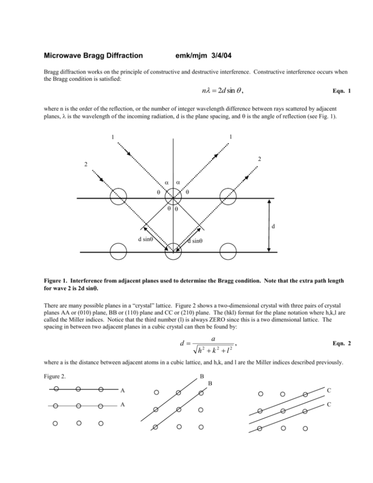
Microwave Bragg Diffraction emk/mjm 3/4/04 Bragg diffraction works on the principle of constructive and destructive interference. Constructive interference occurs when the Bragg condition is satisfied: n 2d sin , Eqn. 1 where n is the order of the reflection, or the number of integer wavelength difference between rays scattered by adjacent planes, is the wavelength of the incoming radiation, d is the plane spacing, and is the angle of reflection (see Fig. 1). 1 1 2 2 d d sin d sin Figure 1. Interference from adjacent planes used to determine the Bragg condition. Note that the extra path length for wave 2 is 2d sin. There are many possible planes in a “crystal” lattice. Figure 2 shows a two-dimensional crystal with three pairs of crystal planes AA or (010) plane, BB or (110) plane and CC or (210) plane. The (hkl) format for the plane notation where h,k,l are called the Miller indices. Notice that the third number (l) is always ZERO since this is a two dimensional lattice. The spacing in between two adjacent planes in a cubic crystal can then be found by: d a h2 k 2 l 2 , Eqn. 2 where a is the distance between adjacent atoms in a cubic lattice, and h,k, and l are the Miller indices described previously. Figure 2. B B A C A C 1. Before beginning the experiment, measure the spacing between adjacent “atoms” (a), and record this value in your lab notebook. HINT: It may be a good idea to measure an entire line of atoms and divide by the number of spaces in order to take a more precise reading. 2. Calculate the d-spacing for the three planes mentioned above (010), (110), and (210). 3. Set the Bragg Cube in the foam positioner so the side of the cube is perpendicular to the incoming microwaves. This will insure that you are looking at the (010) planes. Note: The foam positioner angle reading is (90-) not , so when the cube is perpendicular to the incoming waves the reading is = 0°, and the Bragg angle is 90°. Turn up the gain until you see a decent signal arriving at the receiver. 4. Turn the receiver arm to the smallest possible angle (about 30°) and the foam hub to half that value. Increase the receiver angle and the foam angles in a 2:1 ratio (i.e. 2° in receiver angle for every 1° in foam angle) in steps of about 6° of receiver angle and 3° of foam angle. ( is changing by 3o and 2 by 6o) .Record the receiver current at each foam angle, and make special note of the angles at which the receiver current is a maximum You may need to go to smaller angle increments around the maximum to get a better idea of where the true maximum occurs. Remember these angles are not . 5. Repeat steps 3 and 4 for the (110) planes. NOTE: You will have to change the foam crystal so that the diagonal planes are now perpendicular to the incoming microwaves. 6. Use the 4 x 4 Bragg cube made from aluminum rods. This will allow you to measure the (210) plane in addition to the (010) and the (110). Repeat steps 1-5 for all three planes. Question: How will you place the crystal cube in order to measure your third plane? Think about it, come up with your answer and then discuss with instructor before going on. 7. Make a graph of sin vs. (n/2d) for each maximum angle found above. There should be two points from the ball-bearing crystal, and three from the aluminum rod crystal. Do the points lie more or less along a straight line? Should they? 8. What is the wavelength (with uncertainty) of the incoming microwave radiation using this information? Give some detailed discussion of your uncertainty in the wavelength of the microwave radiation, based on data you took in this experiment. [We will earlier have done a Michelson interferometer measurement of this wavelength.] Your reported value and its uncertainty should be based on this experiment's data only.
