How to explicit message to 1734 Point IO modules to set the range
advertisement
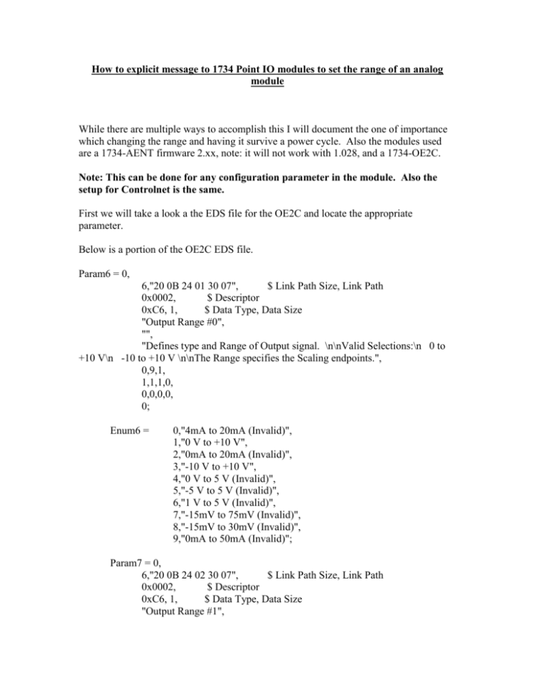
How to explicit message to 1734 Point IO modules to set the range of an analog module While there are multiple ways to accomplish this I will document the one of importance which changing the range and having it survive a power cycle. Also the modules used are a 1734-AENT firmware 2.xx, note: it will not work with 1.028, and a 1734-OE2C. Note: This can be done for any configuration parameter in the module. Also the setup for Controlnet is the same. First we will take a look a the EDS file for the OE2C and locate the appropriate parameter. Below is a portion of the OE2C EDS file. Param6 = 0, 6,"20 0B 24 01 30 07", $ Link Path Size, Link Path 0x0002, $ Descriptor 0xC6, 1, $ Data Type, Data Size "Output Range #0", "", "Defines type and Range of Output signal. \n\nValid Selections:\n 0 to +10 V\n -10 to +10 V \n\nThe Range specifies the Scaling endpoints.", 0,9,1, 1,1,1,0, 0,0,0,0, 0; Enum6 = 0,"4mA to 20mA (Invalid)", 1,"0 V to +10 V", 2,"0mA to 20mA (Invalid)", 3,"-10 V to +10 V", 4,"0 V to 5 V (Invalid)", 5,"-5 V to 5 V (Invalid)", 6,"1 V to 5 V (Invalid)", 7,"-15mV to 75mV (Invalid)", 8,"-15mV to 30mV (Invalid)", 9,"0mA to 50mA (Invalid)"; Param7 = 0, 6,"20 0B 24 02 30 07", $ Link Path Size, Link Path 0x0002, $ Descriptor 0xC6, 1, $ Data Type, Data Size "Output Range #1", "", "Defines type and Range of Output signal. \n\nValid Selections:\n 0 to +10 V\n -10 to +10 V \n\nThe Range specifies the Scaling endpoints.", 0,9,1, 1,1,1,0, 0,0,0,0, 0; Enum7 = 0,"4mA to 20mA (Invalid)", 1,"0 V to +10 V", 2,"0mA to 20mA (Invalid)", 3,"-10 V to +10 V", 4,"0 V to 5 V (Invalid)", 5,"-5 V to 5 V (Invalid)", 6,"1 V to 5 V (Invalid)", 7,"-15mV to 75mV (Invalid)", 8,"-15mV to 30mV (Invalid)", 9,"0mA to 50mA (Invalid)"; From this we see the valid ranges for the outputs are 0 for 4-20mA and 2 for 0-20mA Below is the logic to change the range. In rung 47 the source (oe2c_range_set) is a dint data type and is being copied to the OE2C configuration tag for the range. Valid values for the tag are 0 or 2. In this example I have placed a value of 2 in the tag to change channel 1 range to 0-20mA. In rung 48 we configure a msg instruction. The go to the communications tab and browse to the module. This is what the path ends up being. After this is completed then execute the cop followed by the msg. Now if you open the module properties of the OE2C and go to the configuration tab this is what you should see.
![[#FWDIP-74] PVSS invalid Bits (including range) are not all reflected](http://s3.studylib.net/store/data/007282728_1-8b675e5d894a5a262868061bfab38865-300x300.png)


