fcm-user-guide_v3-2
advertisement
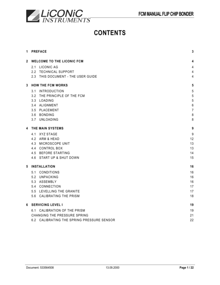
FCM MANUAL FLIP CHIP BONDER CONTENTS 1 PREFACE 3 2 WELCOME TO THE LICONIC FCM 4 2.1 LICONIC AG 2.2 TECHNICAL SUPPORT 2.3 THIS DOCUMENT - THE USER GUIDE 4 4 4 3 HOW THE FCM WORKS 3.1 3.2 3.3 3.4 3.5 3.6 3.7 5 INTRODUCTION THE PRINCIPLE OF THE FCM LOADING ALIGNMENT PLACEMENT BONDING UNLOADING 5 5 5 6 7 8 8 4 THE MAIN SYSTEMS 4.1 4.2 4.3 4.4 4.5 4.6 9 XYZ STAGE ARM & HEAD MICROSCOPE UNIT CONTROL BOX BEFORE STARTING START UP & SHUT DOWN 9 12 13 13 14 15 5 INSTALLATION 5.1 5.2 5.3 5.4 5.5 5.6 16 CONDITIONS UNPACKING ASSEMBLY CONNECTION LEVELLING THE GRANITE CALIBRATING THE PRISM 16 16 16 17 17 18 6 SERVICING LEVEL I 19 6.1 CALIBRATION OF THE PRISM CHANGING THE PRESSURE SPRING 6.2 CALIBRATING THE SPRING PRESSURE SENSOR Document: 533564508 13.09.2000 19 21 22 Page 1 / 22 FCM MANUAL FLIP CHIP BONDER TABLE OF FIGURES Figure 1: The Principle of the FCM ............................................................................................................................................. 5 Figure 2: The Alignment Position................................................................................................................................................ 6 Figure 3: The Head Placement Position ..................................................................................................................................... 7 Figure 4: The Placement (Arm) Movement ................................................................................................................................. 7 Figure 5: The Bonding Movement .............................................................................................................................................. 8 Figure 6: XYZ Stage (Left View) ................................................................................................................................................. 9 Figure 7: The XYZ Stage (Right View) ...................................................................................................................................... 10 Figure 8: XYZ Stage Left Panel ................................................................................................................................................ 11 Figure 9: Motorised Z Head ................................................................................................................................................... 12 Figure 10: A Detail of the Pattern on a Quartz Calibration Reticle. This Detail is Repeated over the Surface of the Chip ............ 19 Figure 11: The Pattern Seen When the 2 Calibration Reticles Are Perfectly Aligned .................................................................. 19 Figure 12: Layout of Pattern on Quartz Calibration Reticle ......................................................................................................... 19 Figure 13: Pattern Showing 6µm Error in Y ................................................................................................................................ 20 Figure 14: Pattern Showing 10 µm Error in X ............................................................................................................................. 20 Figure 15: Pattern Correctly Aligned in ................................................................................................................................... 20 Figure 16: Pattern Mis-Aligned in ............................................................................................................................................ 20 Figure 17: The Layout of the Spring Pressure Sensor ................................................................................................................ 22 Document: 533564508 13.09.2000 Page 2 / 22 FCM MANUAL FLIP CHIP BONDER 1 PREFACE DISCLAIMER The information contained herein is believed to be accurate as of the date of publication. However, LiCONiC AG will not be liable for any damages, including indirect or subsequential, from use of the equipment, or reliance on the accuracy of this documentation. The information contained herein is subject to change without notice. COPYRIGHT The software and documentation are owned by LiCONiC AG and are protected by copyright laws. You may not copy the software, product manuals or written materials which accompany the software. GENERAL CONDITIONS OF GUARANTEE This machine is guaranteed for 1 year against all defects in construction, parts and labour, excluding spare parts not manufactured by LICONIC AG for which the length of guarantee is that given by the manufacturer, eg motors, solenoid valves, integrated circuits, transformers etc. on condition that the defect is acknowledged by LICONIC AG. Any intervention or modification of parts or electronic control circuits carried out without the written permission of LICONIC AG cancels the guarantee. In particular, any tampering with adjustment screws, which are sealed with either wax or varnish, cancels the guarantee. Defective functioning resulting from incorrect adjustment or from the non-respect of the adjustment information is not covered by the guarantee. Guarantee clauses particular to each type of machine are given in the specific technical document and should be read carefully, particularly the information concerning the initial set-up of certain equipment. FOR CERTAIN PIECES OF EQUIPMENT THIS GUARANTEE IS ONLY VALID IF THE MACHINE IS RETURNED TO OUR WORKSHOP. IF THE SERVICE CALL IS CARRIED OUT ON SITE THE TECHNICIAN’S TRAVEL EXPENSES ARE BILLED TO THE USER. CONDITIONS OF OWNERSHIP After the delivery and installation of the equipment and in compliance with the law (article 80.335 of 12 May 80), LICONIC AG remains owner of the equipment supplied until complete payment for it has been received. Furthermore, in the eventuality of non-payment of amounts due, LICONIC AG does not undertake to respect the guarantee. The guarantee will, however, be respected once payment has been made, without the prolongation in time which late payment implies. The data contained in this document is communicated for information only. There is no guarantee as to errors or omissions. The publication of this information does not imply that the contents are exempt from industrial property laws, nor that a licence concerning any one of these laws has been granted (in compliance with clauses of the law of 11 March 1957). What is more, LICONIC AG denies all responsibility as to the consequences of the use of this information, to whatever ends. LICONIC AG reserves the right to modify information concerning the products described, without notice, and also the right to alter the products themselves in order to improve their reliability or their functioning. SERVICE CALLS In order to avoid abuse, every request for the service call of a LiCONiC AG after-sales technician must be confirmed by telex. No other form of request will be acknowledged. In addition, for service calls outside the guarantee period, the telex should include an order number in order to facilitate rapid settlement. The payment of service calls carried out outside the guarantee period is to be made upon receipt of our invoice. No service calls will be carried out if these conditions are not respected. Document: 533564508 13.09.2000 Page 3 / 22 FCM MANUAL FLIP CHIP BONDER 2 WELCOME TO THE LICONIC FCM 2.1 LICONIC AG LiCONiC AG has been developing equipment dedicated to R&D departments and pilot plant lines for almost 10 years. LiCONiC AG is committed to providing optimised process solutions for flip-chip bonding, spin coating exposure and laser marking applications. Investing more than 20% of its revenues in R&D every year, we pride ourselves on our cutting-edge technology and global after-sales support. LiCONiC AG is situated in Nendeln, Principality of Liechtenstein. 2.2 TECHNICAL SUPPORT LiCONiC AG has a team of highly-qualified after-sales engineers ready to support your machine. Their assistance help comes free with the first year of machine ownership. This User Guide is one of a 3 documents which describe the LiCONiC FCM. The others are; Short Notice An outline of the steps required to operate the machine Safety Regulations Essential user safety information - read this FIRST If in doubt, always consult the relevant document before taking your next step. 2.3 THIS DOCUMENT - THE USER GUIDE This user guide contains all the information the user needs to know to operate the FCM. This document also contains an appendix; A. Servicing Level I The user will have to carry out simple servicing, as follows; a. Calibration of the prism b. Changing the pressure spring c. Calibrating the spring pressure sensor For each of the above there is a detailed description of the necessary steps. Document: 533564508 13.09.2000 Page 4 / 22 FCM MANUAL FLIP CHIP BONDER 3 HOW THE FCM WORKS 3.1 INTRODUCTION Like other flip chip machines, the bonding process can be divided into five parts: loading, alignment, placement, bonding and unloading. Each unit on the FCM bonder is designed to carry out these operations as quickly and as accurately as possible. 3.2 THE PRINCIPLE OF THE FCM HEAD TRAVEL POSITION HEAD PLACEMENT POSITION PRISM FOCAL PLANE Z HEAD EYE ARM TRAVEL FROM ALIGNMENT TO PLACEMENT POSITION HEAD TRAVEL POSITION ARM ADJUSTMENT POSITION ARM PIVOT BONDING MOVEMENT PLACEMENT (BONDING) POSITION CHUCK/SUBSTRATE FOCAL PLANE ARM PLACEMENT POSITION XYZ STAGE Figure 1: The Principle of the FCM The FCM flip chip bonder is a very simple, yet cleverly designed, machine. It has all the features you need to carry out successful bonding, including vertical bonding movement and placement separating to ensure no scuffing. 3.3 LOADING The user must load a chip and a substrate onto the machine. The substrate is placed manually on the chuck. The chip can either be placed manually on the head endpiece, or it can be placed on the chuck and then picked up with the arm. A separate loading chuck can be supplied. Both chip and substrate are held in place with vacuum. A chuck and head endpiece, adapted to the test quartz chips, are delivered with the machine. Other designs can be delivered on request. Document: 533564508 13.09.2000 Page 5 / 22 FCM MANUAL FLIP CHIP BONDER 3.4 ALIGNMENT ALIGNMENT POSITION PRISM EYE CHUCK/SUBSTRATE XYZ STAGE Figure 2: The Alignment Position The chip and the substrate need to be aligned prior to bonding. This is carried out with the arm in the alignment position (up). The FCM uses a patented split prism technique to enable you to view the chip and the substrate simultaneously. This method uses only one viewer (camera or microscope) which is fixed, thus eliminating error due to movement. In the alignment sequence, look at the chip and the substrate simultaneously through the microscope or camera. Then adjust (a) the focus of both components (b) the substrate in X and Y and (c) the chip . Alignment is finished when you see the image of the chip and the substrate perfectly coincide. Document: 533564508 13.09.2000 Page 6 / 22 FCM MANUAL FLIP CHIP BONDER 3.5 PLACEMENT After alignment, the chip needs to be placed above the substrate. This is done simple by rotating the arm forward. When the arm starts to move, the head retires back a few millimetres (you can see it). Therefore, when the arm is brought down to the bonding position, the head is separated from the chuck. This avoids scuffing of the chip and substrate and ensures planarity. The actual placement of the chip on the substrate is carried out during the bonding sequence. PRISM EYE Z HEAD PLACEMENT POSITION CHUCK/SUBSTRATE XYZ STAGE Figure 3: The Head Placement Position PRISM EYE ARM TRAVEL FROM ALIGNMENT TO PLACEMENT POSITION PLACEMENT POSITION BONDING POSITION CHUCK/SUBSTRATE XYZ STAGE Figure 4: The Placement (Arm) Movement Document: 533564508 13.09.2000 Page 7 / 22 FCM MANUAL FLIP CHIP BONDER 3.6 BONDING After placement, the arm is in the bonding position. The bonding duration and force are set as necessary. Flicking the “Process” switch carries out the bonding: the head moves down to press the chip against the substrate, the time is counted down (if set), the chip vacuum switches off, and the head lifts back up. PRISM BONDING MOVEMENT EYE BONDING POSITION CHUCK/SUBSTRATE XYZ STAGE Figure 5: The Bonding Movement 3.7 UNLOADING The arm must be moved back up to the alignment position. The bonded component is manually unloaded from the chuck. Care should be taken if heating is used. Document: 533564508 13.09.2000 Page 8 / 22 FCM MANUAL FLIP CHIP BONDER 4 THE MAIN SYSTEMS The machine is composed of the following systems; XYZ Stage Arm & Head Microscope Unit Control Box Structure In addition, the following options are available: Colour camera and monitor Black & white camera and monitor Hot air heating system for BGAs 4.1 XYZ STAGE Figure 6: XYZ Stage (Left View) Document: 533564508 13.09.2000 Page 9 / 22 FCM MANUAL FLIP CHIP BONDER Figure 7: The XYZ Stage (Right View) The XYZ Stage comprises the following; Z unit & adjustment knob XY fine adjustment unit including dX micrometer and dY micrometer Heating Mounting Plate Chuck Process Control Panel Light Control Panel including intensity knob & balance Adjustment Knob (Head Rotation) Air Bearing Button (Stage Lift) The XYZ stage is used to hold, heat and manoeuvre the substrate. It is fitted directly onto the base plate where it is held in place by vacuum and guides. 4.1.1 Z UNIT The Z position of the substrate is adjusted by a knob on the upper right of the stage. This knob is connected directly to four ball screws which raise and lower the mounting plate. This facility allows the substrate to be focused during alignment. It also compensates for different thicknesses of component. This means that the stage can accommodate multi-chip stacking applications. 4.1.2 XY FINE ADJUSTMENT UNIT The fine adjustment unit comprises one micrometer for moving the mounting plate in X and one in Y. The stage remains fixed to the base plate. Document: 533564508 13.09.2000 Page 10 / 22 FCM MANUAL FLIP CHIP BONDER 4.1.3 HEATING MOUNTING PLATE The mounting plate can accommodate substrate sizes up to 160 x 110 mm. The chuck is mounted directly onto the mounting plate with screws. It can easily be replaced with a different chuck to accommodate different sizes of component. 4.1.4 CHUCK The FCM is supplied with a basic chuck which is adapted to the quartz test chips. The user can make chucks adapted to their particular parts or request them from LiCONiC AG. The vacuum supply pipe is attached to the chuck to secure the substrate. 4.1.5 PROCESS CONTROL PANEL The process control panel contains four switches. These switches carry out the following operations: PROCESS Off THE MAGNETS ARE OFF. IF ARM IS DOWN, HEAD IS IN TRAVEL POSITION. Magnets THE MAGNETS ARE ON. Run RUNS THE BONDING CYCLE: 1. IF ACTIVATED, THE TIME STARTS COUNTING DOWN. 2. THE HEAD MOVES DOWN AND APPLIES THE FORCE SET. 3. THE HEAD VACUUM SWITCHES OFF. 4. THE HEAD MOVES UP. On SWITCHES THE HEAD VACUUM ON. HEAD VACUUM HEAD VACUUM ON/OFF ELECTRONICALLY CONTROLLED. Off SWITCHES THE HEAD VACUUM OFF. On THE STAGE VACUUM IS OFF. STAGE VACUUM Off THE STAGE VACUUM IS ON. Off THE MAGNETS ARE OFF. IF ARM IS DOWN, HEAD IS IN PLACEMENT POSITION. Magnets THE MAGNETS ARE ON. Down LOWERS THE HEAD TO THE BONDING POSITION FOR AS LONG AS THE SWITCH IS KEPT PRESSED. NO FORCE. PICK/PLACE Figure 8: XYZ Stage Left Panel 4.1.6 LIGHT CONTROL PANEL The light control panel comprises two knobs: a) Adjusts the light intensity; turn clockwise to increase the light, anti-clockwise to decrease. b) Alters the balance of the light; turn clockwise to light the chip, anti-clockwise to light the substrate. 4.1.7 ADJUSTMENT KNOB The Adjustment Knob is found on the right side of the stage. Turn this knob to rotate the head/chip in . Document: 533564508 13.09.2000 Page 11 / 22 FCM MANUAL FLIP CHIP BONDER 4.1.8 AIR BEARING BUTTON The Air Bearing Button is found on the right side of the stage. Press this knob to activate the stage air pressure to be able to move the stage around the base plate. 4.2 ARM & HEAD The arm & head unit includes: Motorised Z Head Head Heater Head Endpiece (Chip Holder) Pivoting Arm Locking Magnets 4.2.1 MOTORISED Z HEAD Figure 9: Motorised Z Head The head can be rotated through 6° using the control on the right of the XYZ stage. This enables the chip to be aligned to the substrate. 4.2.2 HEAD HEATER The chip is heated via the head heater up to 350°C. The temperature is controlled via the readout on the control box. The rest of the arm is protected from heat conduction by four insulators placed behind the heater. 4.2.3 HEAD ENDPIECE (CHIP HOLDER) The head can accommodate chips up to 40 mm square. The chip is held by vacuum on the head endpiece during alignment. The vacuum pattern is modified to suit the size of the chip and the layout of the bumps. 4.2.4 PIVOTING ARM The arm carries out two important functions between alignment and bonding: Rotates the chip through 90°. This ensures that the chip and substrate are parallel when the arm is brought down into the bonding position. Document: 533564508 13.09.2000 Page 12 / 22 FCM MANUAL FLIP CHIP BONDER Moves the chip back linearly from its alignment position to its travel position. This is to ensure that the chip is separated from the substrate when lowered into the bonding position. The distance displaced is remembered and added to the bonding movement. 4.2.5 LOCKING MAGNETS If a force is used during bonding, the arm needs to be held firmly on position. This is done using 2 locking magnets, which have been tested up to 130 kg. The control system has been designed so that it is not possible to either pick up a chip or carry out a bonding without the magnets being activated. A green LED on the control box shows if the magnets are on. 4.3 MICROSCOPE UNIT The microscope unit comprises: Microscope Superimposing Prism Pre-Alignment Laser Pointer 4.3.1 MICROSCOPE The microscope is a standard Leica Wild M5 unit with an 0.63 objective and 10X eyepieces, giving a magnification of between 4x and 23x 4.3.2 SUPERIMPOSING PRISM Through the prism, the user is able to see the chip and the substrate at the same time. When they are both in focus (using the controls on the stage and the control box), they are the same distance away from the prism. In this way, the user can be sure that, when the chip is brought down into the bonding position, its plane will coincide with that of the substrate. 4.3.3 PRE-ALIGNMENT LASER POINTER In order to facilitate moving the component into the correct position for loading or alignment, a red pointer is fitted to the microscope support. The user can adjust this to shine at the centre of the field of view. They then simply move the component so that it is in the same position as the light. 4.4 CONTROL BOX 4.4.1 OVERVIEW The control box controls the four bonding parameters: Document: 533564508 13.09.2000 Page 13 / 22 FCM MANUAL FLIP CHIP BONDER Head Temperature Stage Temperature Bonding Time Bonding Force It also controls the focus position of the head. 4.4.2 HEAD TEMPERATURE This controller is used to set the temperature of the head, which in turn heats up the chip tool and the chip. Since the speed of heating is slow, the temperature is not varied during bonding, but remains fixed. The maximum temperature is 350°C. Cooling is natural. The temperature is set using the buttons on the controller. Heating comes into effect as soon as it is set. 4.4.3 STAGE TEMPERATURE This controller is used to set the temperature of the stage, which in turn heats up the substrate tool and the substrate. Since the speed of heating is slow, the temperature is not varied during bonding, but remains fixed. The maximum temperature is 300°C. Cooling is natural. The temperature is set using the buttons on the controller. Heating comes into effect as soon as it is set. 4.4.4 BONDING TIME The bonding time is used during a bond when the process switch is used. The bonding time function has two components: Timer and Mode Switch. The Mode Switch determines whether the time function is validated or not. If the Mode Switch is ON, the time function is validated and the time set with the Timer will be counted down during a process. It starts as soon as the head starts moving down (not when the set force is reached). When the set time has been counted down, the head moves back up. The Timer sets bonding time countdown. 4.4.5 BONDING FORCE The FCM is fitted with a pressure sensor feature as part of the force function. It enables a precise bonding force to be set. The force function has four components: 3 digit display “Maximum” adjustment screw for setting the maximum force of the machine. “Zero” adjustment screw for setting the zero force. Force control knob. TO USE 1. Set the force required using the force control knob. Since the display shows the actual force, it will not change. 2. When the head comes down for bonding, the display changes according to the force exerted. 3. The head stops moving when the force set by the knob has been reached. 4. It is possible to vary the force using the knob during bonding. 4.5 BEFORE STARTING Before using, make sure that 1. The machine is plugged in to the mains supply (as well as the camera power supply and monitor if fitted). 2. The utilities (air and vacuum) are connected and turned on. Document: 533564508 13.09.2000 Page 14 / 22 FCM MANUAL FLIP CHIP BONDER WARNING Do not put your fingers between the XYZ stage and the granite base. If the air pressure fails, the air bags are deflated. Your fingers could be jammed. 4.6 START UP & SHUT DOWN POWER ON 1. Make sure the table is flat (spirit level and 13 mm spanner). 2. Switch on the control box (switch at rear right) POWER OFF 1. Switch off heaters by setting them to 0. 2. Switch off the control box (the switch is on the back panel). 3. Disconnect vacuum and pressure. 4. Take off microscope by loosening the screw on the top of the microscope support. Document: 533564508 13.09.2000 Page 15 / 22 FCM MANUAL FLIP CHIP BONDER 5 INSTALLATION 5.1 CONDITIONS Like all flip chip bonders, the FCM requires a clean, stable environment. Any fluctuation in temperature, or any dust, will affect the performance. It needs to be placed on a strong, rigid table. 5.2 UNPACKING The crate carrying the FCM contains the following packages: 1. FCM structure: base, arm and microscope support. 2. Microscope (binocular + viewer) 3. XYZ Stage 4. Control box 5. Control box shelf 6. Stage guide If a camera option has been ordered, there will also be the following packages: 1. Camera, adapter & arm 2. Camera power supply 3. Monitor In addition, there will be a collection of leads and tubes, which need to be connected between the units. 5.3 ASSEMBLY After having unpacked the above, the separate units need to be fitted together. 1. Place the structure on a table. 2. Make sure the arm is in the “back” position. 3. Fit the microscope binocular onto the support. It is locked in position with a screw located on the top of the support. 4. Fit the microscope viewer onto the binocular (it is fixed with a locking screw at the front). 5. Place the stage guide onto the base so that it runs between the rails. 6. Place the stage onto the base between the guides, with one drive on the right and one at the front. 7. Attach the shelf support to the back of the base using the two bolts provided. 8. Fit the shelf onto the top of the shelf support. 9. Place the control box on the shelf. If the camera option has been ordered, do the following: 1. Before placing the viewer on the binocular, fit the camera arm so that it extends to the right. Then, fit the viewer on top of this. 2. Push the camera adapter into the arm socket, using the grub screw to secure it. 3. Screw the camera onto the adapter. Document: 533564508 13.09.2000 Page 16 / 22 FCM MANUAL FLIP CHIP BONDER 5.4 CONNECTION Next, all the units have to be connected and plugged in. All the connectors, cables, leads and tubes are labelled, as follows: Tube/Cable/Lead Connect1 Connect2 Vacuum supply tube (black) Control box rear panel Vacuum supply Air supply tube (blue) Control box rear panel Air pressure supply Head (vacuum) tube (blue) Control box rear panel Underside rear left of arm Chuck (vacuum) tube (blue) Control box rear panel Underside left of stage Stage (vacuum & air) tube (blue) Control box rear panel Underside left of stage Stage cable (grey - round connector) Control box rear panel Left of stage Stage cable (black - flat connector) Control box rear panel Left of stage Lighting cable Control box rear panel Back of construction Arm cable Control box rear panel Underside rear left of arm Plug lead Control box rear panel Mains power supply Also, if a camera is fitted: Tube/Cable/Lead Connect1 Connect2 Image transmission cable (green) Rear of monitor Top of camera Camera power transmission cable (black) Front of camera power supply box Top of camera Power supply lead (black) Already attached to back of camera power supply Mains power supply Monitor lead Rear of monitor Mains power supply 5.5 LEVELLING THE GRANITE The granite base is fitted with five feet to give stability under pressure. These feet need to be levelled to the supporting table, and adjusted so that the top surface of the granite base is horizontal. Tools required: Spirit level 13 mm spanner 1. Screw all four outside feet as far in as possible 2. Screw the middle foot half way in 3. Place a spirit level on the granite surface between the middle foot and the rear right foot 4. Screw out the rear right foot until the granite is level 5. Place a spirit level on the granite surface between the middle foot and the rear left foot 6. Screw out the rear left foot until the granite is level 7. Place the spirit level between the two rear feet to check the levelling of the granite 8. Screw out the two front feet until they come into contact with the table top 9. Adjust the two rear feet if necessary until the granite is level 10. Repeat the above for the two front feet Document: 533564508 13.09.2000 Page 17 / 22 FCM MANUAL FLIP CHIP BONDER 5.6 CALIBRATING THE PRISM Before use, the machine has to be calibrated. It has already been set up a t the factory to ensure squareness, but it is probable that the prism has been moved during transport, and will therefore need to be adjusted. For instructions on this, see the Servicing Level I appendix 6.1 “Calibration of the Prism” on page 19. Document: 533564508 13.09.2000 Page 18 / 22 FCM MANUAL FLIP CHIP BONDER 6 SERVICING LEVEL I 6.1 CALIBRATION OF THE PRISM Equipment needed: 1,27 mm allan key 2 quartz calibration reticles (supplied with machine) CALIBRATION RETICLES Figure 10: A Detail of the Pattern on a Quartz Calibration Reticle. This Detail is Repeated over the Surface of the Chip External square Figure 11: The Pattern Seen When the 2 Calibration Reticles Are Perfectly Aligned Vernier with 1 m precision in Y (each line is 5 µm thick) Squares with dimension 100m Vernier with 1 m precision in X (each line is 5 µm thick) Vernier with 2m precision in Y (each line is 10 µm thick) Internal square Vernier with 2m precision in X (each line is 10 µm thick) Figure 12: Layout of Pattern on Quartz Calibration Reticle Document: 533564508 13.09.2000 Page 19 / 22 FCM MANUAL FLIP CHIP BONDER Figure 14: Pattern Showing 10 µm Error in X Figure 13: Pattern Showing 6µm Error in Y PROCEDURE 1. Place the two reticles on the machine, one on the head (chip), and one on the table (substrate). 2. Align the chip to the substrate. Push/Pull 1 3. Place the chip on the substrate. 4. Look at the result and remember it (draw it if Push/Pull 2 necessary). 5. Pick up the chip and raise the arm (the chip and substrate should still be aligned!) 6. Use the four push-pull screws to adjust the prism so that the image of the chip and substrate is the same as that when the chip was placed (step 4) 7. Move stage still chip and substrate are aligned again 8. Repeat steps 2 to 7 until the result is accurate. Screw 1 adjust 1.Screw 2 adjust 2. Hint To check that the chip and substrate are correctly aligned in , align in X and misalign in Y so that the squares on the reticles overlap. If is correct, the overlap will be the same over the whole surface (see diagram on right). Figure 16: Pattern Mis-Aligned in Figure 15: Pattern Correctly Aligned in Document: 533564508 13.09.2000 Page 20 / 22 FCM MANUAL FLIP CHIP BONDER CHANGING THE PRESSURE SPRING The correct pressure spring must be fitted according to the pressure to be applied. There are three pressure springs: 10g to 1.5 kg, 0.2 to 15 kg (fitted as standard) and 5 kg to 50 kg. Equipment needed: flat screwdriver PROCEDURE 1. Disconnect the vacuum tube and the wiring 2. Replace the magnet from the axis. 3. Pull out the pressuring unit of the head unit. 4. Change pressure spring. 5. Replace pressuring unit into the head unit. 6. Check that the pressure spring can be complete pressed (if not: check position of the linear bushing). 7. Reconnect the vacuum tube and the wiring. 8. Replace the magnet that force sensor shows zero. Document: 533564508 13.09.2000 Page 21 / 22 FCM MANUAL FLIP CHIP BONDER 6.2 CALIBRATING THE SPRING PRESSURE SENSOR Equipment needed: Small flat screw driver Hard weigh scale MAXIMUM FORCE ADJUSTMENT SCREW FORCE DISPLAY HEAD TEMP STAGE TEMP TIME FORCE FORCE CONTROL KNOB MAX FOCUS LOCKED ZERO MODE ON OFF PRESSURE SENSOR ZERO FORCE ADJUSTMENT SCREW FEEDBACK FORCE SPRING CHIP TOOL STAGE Figure 17: The Layout of the Spring Pressure Sensor The pressure is applied to the components via a spring in the head. The spring is attached to a strain gauge that is linked to the control box. The force readout is proportional to the actual force in the spring. The readout can be calibrated using the two adjustment screws “maximum” (or coefficient) and “zero” (or offset). The force sensor is calibrated at the factory. Minimum force is set to zero and maximum force is set in N eg if the 15 kg head is fitted, the maximum will read about 150. However, it is possible for the end user to calibrate the sensor; for setting the maximum, he will need a hard weigh scale. TO SET THE ZERO 1. Move the stage out of the bonding area. 2. Bring the arm down into the bonding position so the head is freely suspended. 3. Using a flat-head screwdriver, set the force display to 0 (or any offset required). TO SET THE MAXIMUM 1. Place the weigh scale in the bonding area, assuring that the surface is approximately in focus. 2. Focus the head. 3. Set the force control knob to maximum. 4. Make sure the timer is off. 5. Bring the arm into the bonding position. 6. Carry out a bonding keeping the process switch down. During this time, read off the value in the scale and set the maximum accordingly by adjusting the screw. Document: 533564508 13.09.2000 Page 22 / 22
