3.052Lecture5AFMImag..
advertisement
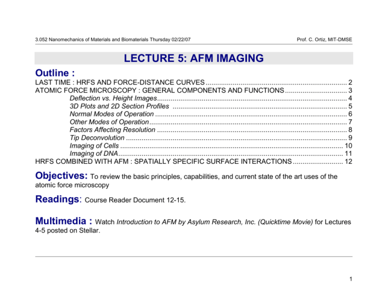
3.052 Nanomechanics of Materials and Biomaterials Thursday 02/22/07 Prof. C. Ortiz, MIT-DMSE I LECTURE 5: AFM IMAGING Outline : LAST TIME : HRFS AND FORCE-DISTANCE CURVES ......................................................................... 2 ATOMIC FORCE MICROSCOPY : GENERAL COMPONENTS AND FUNCTIONS ................................ 3 Deflection vs. Height Images .................................................................................................. 4 3D Plots and 2D Section Profiles .......................................................................................... 5 Normal Modes of Operation ................................................................................................... 6 Other Modes of Operation ...................................................................................................... 7 Factors Affecting Resolution .................................................................................................. 8 Tip Deconvolution .................................................................................................................. 9 Imaging of Cells ................................................................................................................... 10 Imaging of DNA .................................................................................................................... 11 HRFS COMBINED WITH AFM : SPATIALLY SPECIFIC SURFACE INTERACTIONS .......................... 12 Objectives: To review the basic principles, capabilities, and current state of the art uses of the atomic force microscopy Readings: Course Reader Document 12-15. Multimedia : Watch Introduction to AFM by Asylum Research, Inc. (Quicktime Movie) for Lectures 4-5 posted on Stellar. 1 3.052 Nanomechanics of Materials and Biomaterials Thursday 02/22/07 Prof. C. Ortiz, MIT-DMSE HIGH RESOLUTION FORCE SPECTROSCOPY (HRFS) EXPERIMENT : FORCEDISTANCE CURVES (=cantilever deflection) A. tip and sample out of contact B. attractive interaction pulls tip down towards surface C. tip jumps to surface D. tip and sample / z-piezo move in unison G. tip and sample out of contact F. tip releases from surface E. attractive force keeps tip in contact with surface D. tip and sample / z-piezo move in unison retracting -Normal vs. Lateral Force Microscopy repulsive regime kc attractive regime Force, F (nN) approaching 0 Tip-Sample Separation Distance, D (nm) - Conversion of raw data; sensor output, s (Volts) vs. zpiezo displacement/deflection, (nm) to Force, F, versus tip-sample separation distance, D : =s/m m= slope in constant compliance regime =s/ (V/nm) F=k D= z± -zeroing the baseline 2 3.052 Nanomechanics of Materials and Biomaterials Thursday 02/22/07 Prof. C. Ortiz, MIT-DMSE ATOMIC FORCE MICROSCOPY : GENERAL COMPONENTS AND FUNCTIONS laser diode mirror A B C D cantilever sensor output, , F ↓ position sensitive photodetector • spring which deflects as probe tip scans sample surface 10°-15° -Cantilever deflects () in response to an a topographical feature (hill or valley) • measures deflection of cantilever probe tip • senses surface properties and causes cantilever to deflect -Piezo rasters or scans in the x-y direction across the sample surface ERROR = actual signal - set point sample computer ↓ Feedback loop -System continuously changes in response to an experimental output (= cantilever deflection which is the feedback parameter) • controls system • performs data acquisition, display, and analysis piezoelectric z y scanner • positions sample x feedback loop • controls z-sample position (x, y, z) with Å accuracy Advantages : 1) Unlike electron microscopes, samples do not need to be coated or stained, minimal damage, 2) Unlike electron microscopes, samples can be imaged in fluid environments (near-physiological conditions), 3) Unlike STM samples do not need to be conductive, 4) Sub-nm resolutions have been achieved on biological samples (detailed information on the molecular conformation, spatial arrangement, structural dimensions, rate dependent processes, etc.) -Computer adjusts the piezo zdisplacement to keep constant = "setpoint" ↓ Error signal (actual signal-set point) used to produce a topographical (height) map in the z-direction of the surface 3 3.052 Nanomechanics of Materials and Biomaterials Thursday 02/22/07 Prof. C. Ortiz, MIT-DMSE ATOMIC FORCE MICROSCOPY : DEFLECTION VS HEIGHT IMAGES 1.00 nm 1.5 m 0.00 nm Deflection Image: -Raw data output of cantilever deflection from photodiode, very clear, the less feedback the clearer, One can identify and measure high resolution (x/y) spatial dimensions of structural features Height Image: -Processed data from z-piezo, less clear compared to deflection image, maximize your feedback system, can quantify the height of structural features, in 2D image corresponds to brightness zscale bar (e.g. images are a large residual nanoindent of bone using an instrumented indenter and Berkovich diamond probe showing plastic deformation of mineralite nanogranular structure, K. Tai and C. Ortiz Nano Letters, 2006) 4 3.052 Nanomechanics of Materials and Biomaterials Thursday 02/22/07 Prof. C. Ortiz, MIT-DMSE ATOMIC FORCE MICROSCOPY : 3D PLOTS AND 2D SECTION PROFILES z (m) 1.5 7 6 5 Z[Å] 1.0 4 3 0.5 2 1 0 0 0 1.4µm 3D Height image 2D Height image 0 1 2 2 4 3 4 6 5 8 6 7 10 x X[µm] (m) 2D Section Profile -Select linear region of plot and plot 2D section profile (height along line) z vs. x to get quantitative mathematical functional form of topography. For example, we can see the profile of the deformation of indent plus form of plastically deformed "pileup" regions"→ one can use these profiles in conjunction with modeling to extract out material properties such as modulus, yield stress, anisotropy, and strain hardening behavior. -In the next assignment, you will have to use a section profile on nanoparticles to estimate the probe tip radius. (e.g. images are a large residual nanoindent of bone using an instrumented indenter and Berkovich diamond probe showing plastic deformation of mineralite nanogranular structure, K. Tai and C. Ortiz Nano Letters, 2006) 5 3.052 Nanomechanics of Materials and Biomaterials Thursday 02/22/07 Prof. C. Ortiz, MIT-DMSE ATOMIC FORCE MICROSCOPY IMAGING : NORMAL MODES OF OPERATION Contact (DC and AC or Force Modulation) : ● tip remains in contact with sample ● feedback signal, c ● potentially destructive due to high lateral (x/y) forces ● high resolution Intermittent Contact (AC, Tapping) Mode : ● tip is oscillated near its resonant frequency and "taps" on and off the surface ● feedback signal, oscillation amplitude or phase ● less destructive due to reduction of lateral forces ● loss of spatial resolution Noncontact (AC) Mode : ● tip is oscillated near its resonant frequency without touching the surface ● feedback signal, oscillation amplitude ● nondestructive ● loss of spatial resolution ● difficult in practice (Schematic taken from Thermomicroscopes, Introduction to AFM) 6 3.052 Nanomechanics of Materials and Biomaterials Thursday 02/22/07 Prof. C. Ortiz, MIT-DMSE ATOMIC FORCE MICROSCOPY IMAGING : OTHER MODES OF OPERATION I. Normal Force Microscopy Contact DC and AC Intermittant Contact/ (Force Modulation Tapping / Lift (AC) Noncontact (NC) 1995 Microscopy (FMM), Phase Imaging) Hansma, et al., 1991 Hansma, et al., 1994 II. Friction or Lateral Force Microscopy (FFM/ LFM) Frisbie, et al., 1994 http://www.di.com/AppNotes/LatChem/LatChemMain.html III. Force / Volume Adhesion Microscopy chemicallyfunctionalized probe tip: X=-OH,-CH3,-NH2 X X X X X X X X X X X X X X X X X X X Radmacher, et al., 1994 X http://www.di.com/AppNotes/ForceVol/FV.array.html Surface Maps: IV. Chemical Force Microscopy (CFM) Frisbie, et al., 1994 Topography & Roughness, Electrostatic Interactions, Friction Chemical, Adhesion , Hardness, Elasticity /Viscoelasticity Dynamic Processes : Erosion, Degradation, Protein-DNA Interactions 7 3.052 Nanomechanics of Materials and Biomaterials Thursday 02/22/07 Prof. C. Ortiz, MIT-DMSE Hoh, et al. Biophys. J. 1998, 75, 1076. D+D d -Z D L+L ~ +Z L voltage applied -X +Y +X Force, F (nN) ATOMIC FORCE MICROSCOPY IMAGING : FACTORS AFFECTING RESOLUTION SPECIMEN PIEZO AMPLIFIER, SENSOR AND ADHESION FORCE DEFORMATION & CONTROL ELECTRONICS, Yang, et al. Ultramicroscopy 1993, 50, 157 MECHANICAL PARAMETERS THERMAL Physik Instruments, Nanopositioning 1998 FLUCTUATIONS y Distance, D (nm) x connecting wires Fadhesion 0 z electrodes 0 polarization PROBE TIP SHARPNESS CANTILEVER THERMAL NOISE (*http://cnst.rice.edu/pics.html Lieber, et al., 2000) Sheng, et al. J. Microscopy 1999, 196, 1. Lindsay Scanning Tunneling Microscopy and Spectroscopy 1993, 335. kt Shao, et al. Ultramicroscopy 1996, = 66, 141. m cantilever t(max) t(max) m m 8 3.052 Nanomechanics of Materials and Biomaterials Thursday 02/22/07 Prof. C. Ortiz, MIT-DMSE ATOMIC FORCE MICROSCOPY IMAGING : TIP DECONVOLUTION -Imaging very sharp vertical surfaces is influenced by the sharpness of the tip. Only a tip with sufficient sharpness can properly image a given z-gradient. Some gradients will be steeper or sharper than any tip can be expected to image without artifact. False images are generated that reflect the self-image of the tip surface, rather than the object surface. Mathematical methods of tip deconvolution can be employed for image restoration. The effectiveness of these methods will depend on the specific characteristics of the sample and the probe tip. probe tip scan direction square nanoobject w/2 substrate r* 9 3.052 Nanomechanics of Materials and Biomaterials Thursday 02/22/07 Prof. C. Ortiz, MIT-DMSE ATOMIC FORCE MICROSCOPY IMAGING OF CELLS Contact mode image of human red blood cells - note cytoskeleton is visible. blood obtained from Johathan Ashmore, Professor of Physiology University College, London. A false color table has been used here, as professorial blood is in fact blue. 15µm scan courtesy M. Miles and J. Ashmore, University of Bristol, U.K. Radmacher, et al., Cardiac Cells http://www.physik3.gwdg.de/~radmacher/ Red Blood Cells Shao, et al., : http://www.people.virginia.edu/~js6s/zsfig/random.html Rat Embryo Fibroblast (*M. Stolz,C. Schoenenberger, M.E. Müller Institute, Biozentrum, Basel Switzerland) Height image of endothelial cells taking in fluid using Contact Mode AFM. 65 µm scan courtesy J. Struckmeier, S. Hohlbauch, P. Fowler, Digital Intruments/Veeco Metrology, Santa Barbara, USA. 10 3.052 Nanomechanics of Materials and Biomaterials Thursday 02/22/07 Prof. C. Ortiz, MIT-DMSE ATOMIC FORCE MICROSCOPY IMAGING OF DNA TappingMode image of nucleosomal DNA. Image courtesy of Y. Lyubchenko. Image of PtyrTlac supercoiled DNA. 750 nm scan courtesy C. Tolksdorf, Digital Instruments/Veeco, Santa Barbara, USA, and R. Schneider and G. Muskhelishvili, Istitut für Genetik und Mikrobiologie, Germany. http://www.people.virginia.edu/~js6s/zsfig/DNA.html The high resolution of the SPM is able to discern very subtle features such as these two linear dsDNA molecules overlapping each other. 155nm scan. Image courtesy of W. Blaine Stine AFM image of short DNA fragment with RNA polymerase molecule bound to transcription recognition site. 238nm scan size. Courtesy of Bustamante Lab, Chemistry Department, University of Oregon, Eugene OR 11 3.052 Nanomechanics of Materials and Biomaterials Thursday 02/22/07 Prof. C. Ortiz, MIT-DMSE HRFS COMBINED WITH AFM : SPATIALLY SPECIFIC SURFACES INTERACTION INFORMATION 0.4 1 m Position 1 Position 2 Position 3 Position 4 Position 5 Position 6 Position 7 4 3 2 1 Grain 1 5 Grain 3 6 7 Force (nN) Grain 2 3 0.2 2 0.1 1 0.0 0 0 5 10 Distance from Surface (nm) Force/Radius (mN/m) 0.3 4 15 ● AFM can be combined with high resolution force spectroscopy and nanoindentation since cantilever probe tip can be employed for both imaging and nanomechanical measurements→ nanomechanical measurements with positional accuracy down to the nanoscale (Vandiver, et al. Biomaterials 26 (2005) 271–283). 12
