POLA_24924_sm_SuppInfo
advertisement
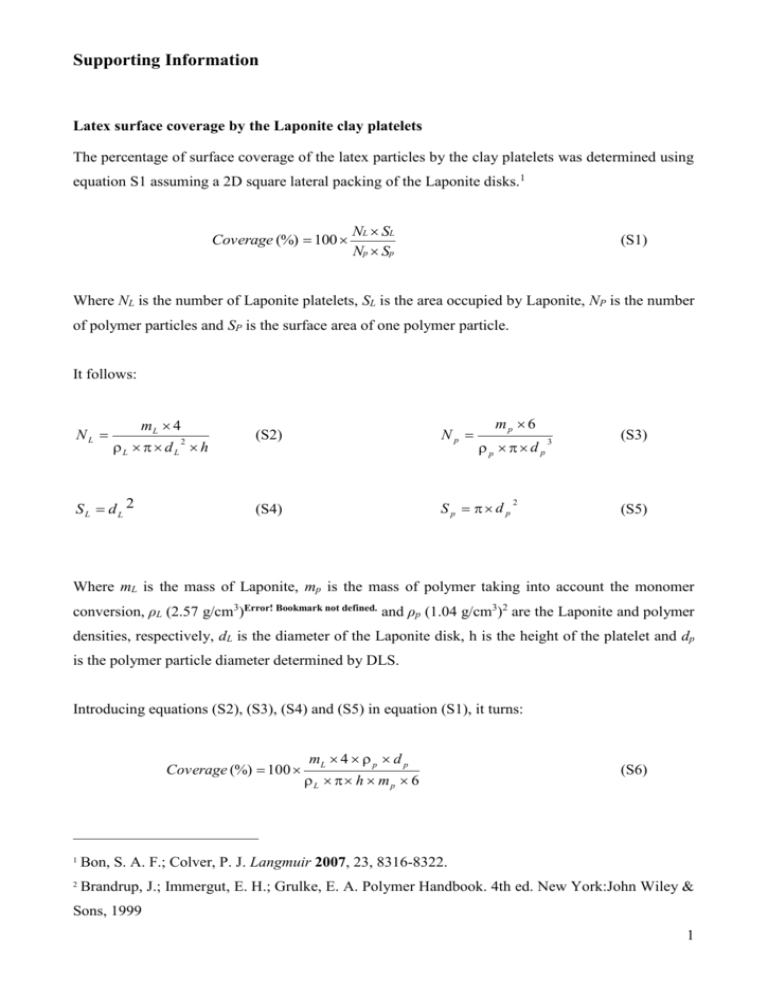
Supporting Information Latex surface coverage by the Laponite clay platelets The percentage of surface coverage of the latex particles by the clay platelets was determined using equation S1 assuming a 2D square lateral packing of the Laponite disks.1 Coverage (%) 100 NL SL Np Sp (S1) Where NL is the number of Laponite platelets, SL is the area occupied by Laponite, NP is the number of polymer particles and SP is the surface area of one polymer particle. It follows: NL mL 4 L d L h SL dL 2 2 mp 6 (S2) Np (S4) Sp d p p d p 2 3 (S3) (S5) Where mL is the mass of Laponite, mp is the mass of polymer taking into account the monomer conversion, ρL (2.57 g/cm3)Error! Bookmark not defined. and ρp (1.04 g/cm3)2 are the Laponite and polymer densities, respectively, dL is the diameter of the Laponite disk, h is the height of the platelet and dp is the polymer particle diameter determined by DLS. Introducing equations (S2), (S3), (S4) and (S5) in equation (S1), it turns: Coverage (%) 100 mL 4 p d p L h mp 6 (S6) 1 Bon, S. A. F.; Colver, P. J. Langmuir 2007, 23, 8316-8322. 2 Brandrup, J.; Immergut, E. H.; Grulke, E. A. Polymer Handbook. 4th ed. New York:John Wiley & Sons, 1999 1 Heat and material balances The heat balance of a semi-continuous reactor is given by: UA T T F C Tfeed MC P T Q T Q R feed Pfeed loss j Q cum Q j (S7) Qfeed The heat produced by the reaction is related to the reaction rate, RP, as follows: H R Q R P (S8) by the following relationship: The monomer conversion, X, can be estimated from Q R t X Q R (S9) 0 H N T NT is the total number of moles of monomer introduced into the reactor and can be calculated by integrating the monomer flow rate, F, added to the initial number of moles of monomer, N0: t N T N 0 F dt (S10) 0 The residual number of moles of monomer in the reactor can be calculated using the monomer conversion as follows: N N T 1 X (S11) Calculation of the concentration of monomer in the polymer particles depends on the reaction interval. During intervals I and II, monomer droplets are present and therefore the polymer particles can be assumed to be saturated with monomer. Hence, interval I corresponds to the nucleation period and interval II to their growth under saturation. In interval III, monomer droplets are completely consumed and all the monomer is supposed to be in the polymer particles (for water 2 insoluble monomers). It can be deduced that [MP] is constant during interval II, and in interval III all the residual monomer is in the polymer particles which gives the following equations: 1 PP m MWm [M P ] N T MWm N N N m P if N 1 PP P m P NT N p 0 (S12) else The reaction rate is related to the concentration of monomer and number of moles of radicals in the polymer particles, [MP] and , by the following relationship: R P k P (T ) n N P V / N A [ M P ] (S13) With the measurement of the monomer conversion, the residual amount of monomer, N, as well as [MP], can be calculated. The reaction rate can then be calculated using equation S8. Subsequently, can be estimated. If the particle size is measured, an estimation of the particle number can be deduced which allows the estimation of n with time. Notations: A: Heat transfer area between the reactor and the jacket (m²) CP: Heat capacity of the reaction medium (J.kg-1.K-1) CPfeed: Heat capacity of the feed (J.kg-1.K-1) Ffeed: Inlet mass flow rate (kg.h-1) kP: Propagation rate coefficient (m3.mol-1.h-1). MWm: Monomer molecular weight (kg.mol-1) M: Total mass of species present into the reactor (kg) NP: Number of particles per liter (-) NA: Avogadro’s number (mol-1) n : Average number of radicals per particle (-) : Heat exchange between the reactor and the jacket (W) Q j Q feed : Flow of heat caused by the addition of reagents (W) Q loss : Heat losses through the condenser or other non jacketed parts of the reactor (W) RP: Reaction rate (mol.h-1) T: reactor temperature (K) 3 Tfeed: Inlet temperature (K) V: Reaction volume (m3) U: Heat transfer coefficient (W.m-².K-1). PP: Fraction of polymer in the particles (-) m: monomer density (kg.m-3) p: Polymer density (kg.m-3) (-H): Reaction enthalpy (J.mol-1) Characterization of the clay-armored latex particles Insert FIGURE S1 here Figure S1: TEM image of a ultra thin cross section of the clay-armored latex particles after embedding in a resin showing that the clay platelets are located at the particle surface and not encapsulated. 4
