Lecture D34 : Coupled Oscillators Spring
advertisement
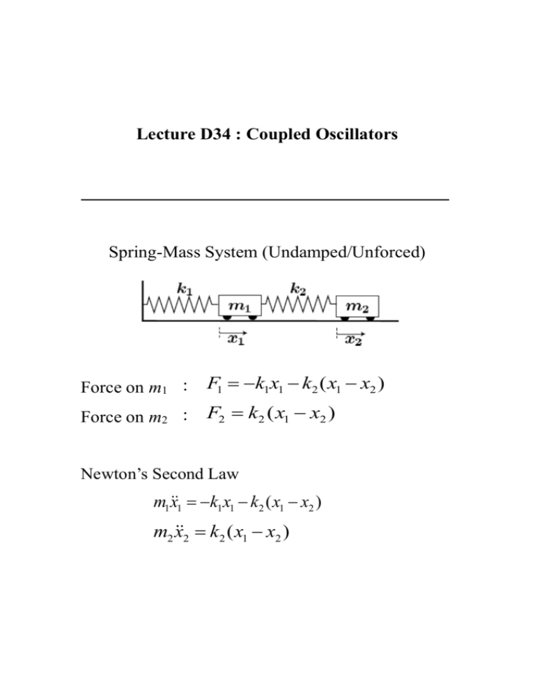
Lecture D34 : Coupled Oscillators Spring-Mass System (Undamped/Unforced) Force on m1 : F1 k1x1 k2 ( x1 x2 ) Force on m2 : F2 k2 ( x1 x2 ) Newton’s Second Law m1 x1 k1 x1 k2 ( x1 x2 ) m2 x2 k2 ( x1 x2 ) Solution Try solution of the form: x1 (t ) X1 sin(t ), x2 (t ) X 2 sin(t ) and see if we can find X1, X2, ω and φ such that the equation is satisfied or , where , Natural Frequencies For non-trivial solutions we need 2 We can solve for ω , where, We can show Normal Modes X1 and X2 will satisfy . . . the same equation!! General Solution Unforced Problem X Constants 1 , to be determined as a function of initial conditions x1 (0), x2 (0), x1 (0) and x2 (0) Note that X 2 are determined once X 1 are known Forced Oscillation Spring-Mass System (Undamped) Newton’s Second Law Solution x1c (t ) and x2c (t ) are solutions of the unforced problem and we already know p p We try a particular solution, x1 (t ) and x2 (t ) of the form p p We can solve for X 1 and X 2 if D ( ) 0 Solution (cont’d) Recall Response for m1= m2, k1= k2 Manuel Martinez-Sanchez, 1996 COUPLED OSCILLATORS This lecture serves a dual purpose: it introduce the concept of independent superimposed harmonic motions, and it allows consideration of simple vibration damping techniques. 1. A Simple Example With Two Coupled Oscillators 1.1. Formulation Consider two masses sliding without friction on a horizontal surface, and connected by spring with no external forces applied. The E1 and E2 are the equilibrium. M1 in the given position is –k1x1-k2(x1-x2) , and the force on M2 is k2(x1- x2). Hence This pair of 2nd order, coupled, constant coefficient differential equations admits oscillatory solutions, which can be represented as Here Re represents the real of a complex quantity, and x1 , x2 are complex numbers. The unknown frequency ω is a real number for this problem, as will be proven, but in more complicated situations, it may also have an imaginary part. If the quantities x1 , x2 have amplitudes x1 , x2 and phase angles 1 , 2 : Then, from the definitions (3), Courtesy of Prof. Martinez-Sanchez. Used with permission. and we could instead have assumed these sinusoidal functions for the solutions. However, the exponential forms in (3) have definite advantages in terms of algebraic cleanliness. Substituting (3) into (1) and (2), we obtain Clearly, these conditions are satisfied of the two square brackets are zero: 1.2 The Natural Frequencies An obvious solution is x1 x2 0 , but we are after a solution where something happens. The only order other possibility is that (8) and (9) are really the same equation, or, in different words, that the two linear homogeneous equations (8) and (9) be compatible. The first viewpoint would imply that the coefficients of x1 , x2 are proportional in both equations: and the second viewpoint (compatibility) would amount to equating to zero the deieminant of the coefficients, which, clearly, leads to the same eq.(Eq. 10). In future, more involved problems, this second approach will be generally followed, because it is the more general of the two. Eq.(10) can be reduced to a 4th order Eq in ω, or, luckily in this case, a 2nd equation in ω2. The absence of terms in ω and ω3 can be traced back to the absence of damping terms, i.e., there is no force proportional to x1 or x2 . Cases with damping can also be handled by the same methods, and we will later see some examples. The equation in this case is The explicit solutions for ω2 are Courtesy of Prof. Martinez-Sanchez. Used with permission. The expression under the radical can be transformed to which is strictly positive, showing that both ω2 values are real. It is also clear from (12) that the square root is smaller in magnitude than the term preceding it, so that both ω2 values are positive, Calling them 2 and 2 , their roots , and are the four roots of Eq. (11). 1.3 The Normal Modes For some purposes, knowing the two natural frequencies 1 , 2 of the system may be all that’s required. But there is more information we can obtain about the kind of oscillations that are possible. Returning to the system (8)-(9), we recall that it really was one single equation, so that only the ratio x2 / x1 has also two corresponding values. For instance, from (8), where 1 stands for or , and there is a x2 / x1 , for each of these. Note that if we had used Eq. (9) instead, we would get the same results, since the ' s have been precisely selected to ensure this. We therefore can construct two different oscillatory solutions of the type of Eqs. (5), each having a different frequency and different relative amplitudes (and phase angles) for the motions of the separate masses. Which of these (or what linear superposition of them) actually occurs depends only one on the initial conditions. There are called the Normal Modes of the system. If we substitute the solutions (12), with (12b) for the radicand, into (13), we find Since the root is now larger in magnitude than the term ahead of it, the (+) choice leads to a negative x2 / x1 and the (-) choice to a positive x2 / x1 . In terms of the phase angles 1 and 2 (Eqs. 4), we see that in the mode with the lower natural frequency, , both x1 and x2 oscillate in phase with each other (and with some definite ratio xˆ2 / xˆ1 of amplitudes), while in the mode with the higher frequency, , they oscillate in counterphase (and with some other amplitude ratio). This can be represented geographically as in Fig. 2, where the mode amplitudes have been represented as While each of these is a purely periodic oscillation of the system, the general superposition of modes is not periodic, any may appear quite chaotic to the untrained eye. For many practical problem, one needs to solve the inverse problem, namely isolating the natural modes and frequencies of an unknown dynamical system from time series data of its complex oscillations. It can be starting to recognize that seemingly very complicated non-periodic patterns can indeed be constructed out of very simple purely periodic modes, in each of which everything in the system oscillates in lock-step. 2. Forced Oscillations We return to our example of Sec. 1, and add the stipulation that an external disturbing force acts on M1. This force has zero average, but oscillates sinusoidally in time with some amplitude F and frequency ω. We can arbitrarily choose the phase of this force variation as zero, and measure those of motions x1, x2 with reference to it. In complex exponential notation, Notice at this point one essential difference to the analysis in Section 1: Here ω is given, and is generally different from the natural frequencies , we found for the un-forced system. Eq.(1) gets modified to and Eq.(2) remains unchanged. As in all linear problems, the general solution will be made up of the homogeneous (the un-forced) solution, plus any particular solution to the inhomogeneous equations. To look for this latter, piece, we anticipate that all parts of the system will react to an excitation at ω by oscillating at this same ω, although generally not in phase with the excitation. Therefore, we again seek solutions of the form (4), but for the specific given ω, and, of course, including F. Substituting into Eqs. (16) and (2), we now have Unlike the system of (8) and (9), this one can indeed be solved for both complex amplitudes xˆ1 , xˆ2 , provided the determination of the coefficients is not zero, i.e., provided and . The solution is where D() m1m2 m1k2 m2 (k1 k2 ) k1k2 is the same polynomial whose roots 4 2 where earlier found to be the natural frequencies , , and can therefore be written more compactly as So, for a given force amplitude F, the masses execute forced oscillations of amplitudes given by (19) and (20). Since xˆ1 , xˆ2 are in general complex, these equations give both the magnitude and the phase (leading or lagging with respect to F) of these displacements. In this particular problem, however, 2 is real, and so xˆ1 / Fˆ and xˆ2 / Fˆ will also be real, but they can still be positive (motion in phase with F) or negative (motion in counterphase). Notice that the ratio x1 / x2 of these amplitudes is precisely the same as we found for the free oscillations in Sec. 1. Let us examine these expressions more closely. ( 2 2 2 ) ), we obtain D k1k2 and then xˆ1 At very low frequencies Fˆ Fˆ , xˆ2 . These are the static k1 k1 deflections under F, say, 0.3 of the fundamental frequency (quasi-static response). approaches , D 0 and both x̂1 and x̂2 tend to infinity (resonance). When the amplitudes become again finite. The ratio x1 / x2 was found in Sec.1 to be positive at , and remains so in this case, below and for some range above . But as As increases further, Eq.(19) shows that x̂1 crosses zero when 2 k2 / m2 . Beyond this point, x̂1 and x̂2 oscillate in counterphase. For even larger , we approach , and a new resonance is observed, with x̂1 and x̂2 diverging in opposite directions. Past , the amplitudes decay with further increases in , and when 2 2 , both approach zero: Clearly, inertia dominates at these very high frequencies, especially in the case of m2, which must be itself forced from the oscillations of m1, through the soft spring k2. This behavior is illustrated in Fig.3 (from Ref. 1) which is for k1=k2, m1=2m2. The quantities x and are a xˆ /( F / k1 ) , xˆ2 /( F / k1 ) , the quantity p is our , and p0 k1 / m1 is the natural frequency with m2 removed. 3. Tuned Dampers The fact that x̂1 crosses zero at some intermediate frequency can be exploited in applications where periodic shaking of a well defined frequency occurs and we wish to protect some part of a system against it. In the example in Fig.3, we can see this effect at 2k1 / m2 k2 / m2 . Here, m1 will not move at all if forced at that frequency, despite the fact that F is directly applied to m1, and this for any amplitude of F! What happens is that F gets “shunted” to m2, which does have a finite amplitude, but this may be acceptable. An example, also from Ref. 1, is shown in Fig. 4, where we protect the floor Clearly, if this is done, care must be taken not excite the new resonance at which is thereby introduced. Tuned dampers of this sort are commonly used on rotating shafts and other machine parts exposed to periodic forcing. Reference Ref. S. Timoshenko and D.H. Young, Advanced Dynamics. McGraw-Hill, 1984. Courtesy of Prof. Martinez-Sanchez. Used with permission.
