Host laboratory role in the test and selection of STANAG
advertisement
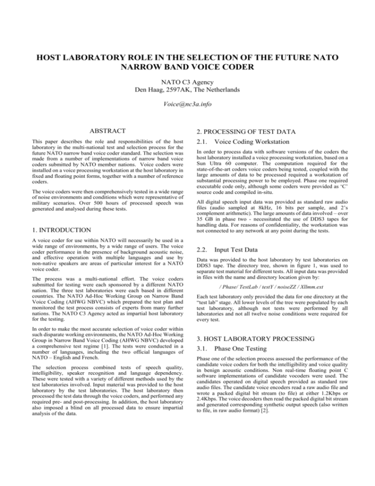
HOST LABORATORY ROLE IN THE SELECTION OF THE FUTURE NATO NARROW BAND VOICE CODER NATO C3 Agency Den Haag, 2597AK, The Netherlands Voice@nc3a.info ABSTRACT This paper describes the role and responsibilities of the host laboratory in the multi-national test and selection process for the future NATO narrow band voice coder standard. The selection was made from a number of implementations of narrow band voice coders submitted by NATO member nations. Voice coders were installed on a voice processing workstation at the host laboratory in fixed and floating point forms, together with a number of reference coders. The voice coders were then comprehensively tested in a wide range of noise environments and conditions which were representative of military scenarios. Over 500 hours of processed speech was generated and analysed during these tests. 1. INTRODUCTION A voice coder for use within NATO will necessarily be used in a wide range of environments, by a wide range of users. The voice coder performance in the presence of background acoustic noise, and effective operation with multiple languages and use by non-native speakers are areas of particular interest for a NATO voice coder. The process was a multi-national effort. The voice coders submitted for testing were each sponsored by a different NATO nation. The three test laboratories were each based in different countries. The NATO Ad-Hoc Working Group on Narrow Band Voice Coding (AHWG NBVC) which prepared the test plan and monitored the test process consists of experts from many further nations. The NATO C3 Agency acted as impartial host laboratory for the testing. In order to make the most accurate selection of voice coder within such disparate working environments, the NATO Ad-Hoc Working Group in Narrow Band Voice Coding (AHWG NBVC) developed a comprehensive test regime [1]. The tests were conducted in a number of languages, including the two official languages of NATO – English and French. The selection process combined tests of speech quality, intelligibility, speaker recognition and language dependency. These were tested with a variety of different methods used by the test laboratories involved. Input material was provided to the host laboratory by the test laboratories. The host laboratory then processed the test data through the voice coders, and performed any required pre- and post-processing. In addition, the host laboratory also imposed a blind on all processed data to ensure impartial analysis of the data. 2. PROCESSING OF TEST DATA 2.1. Voice Coding Workstation In order to process data with software versions of the coders the host laboratory installed a voice processing workstation, based on a Sun Ultra 60 computer. The computation required for the state-of-the-art coders voice coders being tested, coupled with the large amounts of data to be processed required a workstation of substantial processing power to be employed. Phase one required executable code only, although some coders were provided as ‘C’ source code and compiled in-situ. All digital speech input data was provided as standard raw audio files (audio sampled at 8kHz, 16 bits per sample, and 2’s complement arithmetic). The large amounts of data involved – over 35 GB in phase two - necessitated the use of DDS3 tapes for handling data. For reasons of confidentiality, the workstation was not connected to any network at any point during the tests. 2.2. Input Test Data Data was provided to the host laboratory by test laboratories on DDS3 tape. The directory tree, shown in figure 1, was used to separate test material for different tests. All input data was provided in files with the name and directory location given by: / Phase/ TestLab / testY / noiseZZ / Xllmm.ext Each test laboratory only provided the data for one directory at the “test lab” stage. All lower levels of the tree were populated by each test laboratory, although not tests were performed by all laboratories and not all twelve noise conditions were required for every test. 3. HOST LABORATORY PROCESSING 3.1. Phase One Testing Phase one of the selection process assessed the performance of the candidate voice coders for both the intelligibility and voice quality in benign acoustic conditions. Non real-time floating point C software implementations of candidate vocoders were used. The candidates operated on digital speech provided as standard raw audio files. The candidate voice encoders read a raw audio file and wrote a packed digital bit stream (to file) at either 1.2Kbps or 2.4Kbps. The voice decoders then read the packed digital bit stream and generated corresponding synthetic output speech (also written to file, in raw audio format) [2]. In Test phase /phase1 Test lab Test type /Arcon /test1 /test2 /test3 /test4 /phase2 /CELAR /TNO /test5 One raw audio file LPC10e CVSD CELP FR1200 FR2400 TU1200 TU2400 US1200 US2400 B I T S T R E A M LPC10e CVSD CELP FR1200 FR2400 TU1200 TU2400 US1200 US2400 MNRU 5db MNRU 10dB MNRU 15dB Noise Condition /noise01 /noise02 ….. /noise12 MNRU 20dB MNRU 25dB Files for test Xllmm.ext Xllmm.ext X = gender m/f ll = speaker identifier mm = phrase number ext = data type .raw (raw audio) or .08K (8kHz sampled data) Figure 1: Input data directory and file structure 1: Processing input data through voice coders with The useFigure of three national test laboratories, each a specialist different test methods and languages ensured that the candidate coders for STANAG 4591 were exposed to a rigorous and varied testing process. In phase one, all coders were assessed in a limited number of noise environments e.g. quiet; modern office; and non-stationary speech-shaped noise (at 12 dB and 6 dB signal to noise ratios). In general, each speech file from the test laboratories was processed through nine voice coders – three candidate vocoders, each at two Encode Decode LPC10e LPC10e CVSD CELP Single raw audio file FR1200 FR2400 TU1200 TU2400 B I T S T R E A M CVSD CELP FR1200 FR2400 TU1200 Nine raw audio output files Sent to test labs for analysis TU2400 US1200 US1200 US2400 US2400 MNRU 30dB Xllmm.ext Figure 2: Processing of input data through voice coders data rates, plus three reference coders. For calibration of the Mean Opinion Score (MOS) tests for both the US and NL test labs, the speech material was also passed through Modulated Noise Reference Unit (MNRU) software from the International Telecommunications Union (ITU). This adds known levels of noise to speech signals. For these tests eight MNRU levels were used - 5 dB, 10 dB, 15 dB, 20 dB, 25 dB, 30 dB, 35 dB and 40 dB SNR. In phase one the voice coders were tested for speech quality using the Mean Opinion Score (MOS) test which was conducted by two test laboratories in multiple languages. Phase one intelligibility tests were performed by all three test laboratories but with different tests. The Consonant-Vowel-Consonant (CVC) test, the Diagnostic Rhyme Test (DRT) and the Intelligence Transmission (IntelTrans) test were used. MNRU 35dB Nine raw audio output files from codecs 17 raw audio output files. MNRU files to test labs as references for analysing speech quality MNRU 40dB Figure 3: Input data and MNRU processing 3.2. Pre- and Post-Processing The different types of tests employed within the test plan meant that processing for input and output data varied. Some tests required only short input stimuli. In order to remove any edge effects during the start and end phases of the voice coder operation short input files were concatenated prior to processing. Concatenation was performed using the ITU Software Toolkit (STL2000). After processing concatenated data through the voice coders the output file was cut using the astrip command in the Software Toolkit. An additional (dummy) file inserted at the start of the concatenated input was discarded from the stripped output. Preand post-processing was required in both phase one and phase two. 3.3. Phase Two Testing Phase two of the selection process extended the range of acoustic noise environments and the speech characteristics tested. In addition, phase two candidate coders were restricted to fixed point C source code versions as would be used in practical implementations in voice communication terminals. In phase two, the coders were once again installed on the NC3A speech processing workstation. However, executable code for all coders was compiled on the workstation from source code. This, coupled with restrictions on the ‘C’ libraries available during compilation, allowed verification that the coders used only fixed-point operations. Phase two repeated all of the phase one tests for intelligibility and speech quality, but also performed these tests over a wider range of acoustic noise conditions. These additional acoustic noise conditions were both harsher and more representative of the worse case NATO operational scenarios. The harsh acoustic noise environments selected were the Mobile Command Enclosure (MCE) field shelter, staff car, wheeled military vehicle (HMMWV and P4), helicopter (UH60 Black Hawk), tracked vehicle (M2A2 Bradley fighting vehicle and LeClerc tank) and supersonic aircraft (F-15 and Mirage 2000). Voice coder ‘tandem’ and channel error conditions are two practical environments in which military voice coders operate. These cases were tested in phase two for both speech quality and intelligibility. The random bit error channel test uses a 1% random bit error pattern applied to the digital bit stream files. In the case of the ‘tandem’ condition, the speech passed through two complete voice coding algorithms. First, the 16Kbps CVSD algorithm followed by the candidate algorithms. The two voice coders in the tandem test are complete in that they each take speech in, write out digital bit streams (to files), and produce output speech. laboratory for appropriate evaluation. It should be noted that the test laboratories had no information pertaining to the identity of the voice coding algorithms which they evaluated. 1% random bit errors Audio input file Bitstream Coder n Decoder n Audio output file Out Test phase /phase1 /phase2 Test configuration: 1% Bit error rate Test lab Audio input file CVSD Coder B i t s CVSD Decoder A u d i o B i t s Coder n Decoder n Audio output file Test type Noise Condition /Arcon /test1 /test2 /CELAR /test3 /noise01 /noise02 ….. /TNO /test4 /test5 /noise12 Test configuration: Voice coder tandem Coder Figure 4: Phase two additional test configurations Additional types of tests were conducted in phase two. These were speaker recognisability and language dependency tests. Coders were also tested for performance with whispered speech. The whispered speech test uses the Dutch (TNO) Speech Reception Threshold (SRT) intelligibility test for evaluation. 4. BLINDING PROCESS To mask the identities of all voice coders and guarantee impartiality during the analysis of individual voice coders, a blinding process was applied by the host laboratory to all processed material before it was sent for analysis by the test laboratories. Decoded output files Single blinded files Double blinded files LPC10e Coder1 Vocoder1 CVSD Coder2 Vocoder2 CELP Nine audio output files FR1200 FR2400 B Coder3 B L L Vocoder4 I Coder5 I Vocoder5 TU1200 N Coder6 N Vocoder6 TU2400 D Coder7 D Vocoder7 US1200 Coder8 US2400 Coder9 Blinded by NC3A To test lab Vocoder8 Vocoder9 Blinded by DSTL Figure 5: Double blinding process 4.1. Files for test /coder2 Xllmm.out …….. Xllmm.out /coder9 Xllmm.out Figure 6: Output directory structure In phase one a single blind was applied by the host laboratory to the data, prior to evaluation by the test laboratories. In phase two, for added integrity, a double blind was carried out where the NC3A host laboratory performed the initial blinding, with a second blinding operation carried out by an impartial member of the NBVC AHWG. The double blind was carried out in isolation and provided a static re-labeling of all ‘coder n’ to ‘vocoder m’. The result is that neither the NC3A personnel nor the impartial NBVC representative responsible for the second blinding operation are aware of the identities of the nine coders. 5. CONCLUSIONS Vocoder3 Coder4 /coder1 Output File Structure All processed files were stored in a directory structure similar to that of the input material. The only difference was the addition of an extra level in the directory tree which was used to separate the output from each of the voice coders, shown in figure 6. The output from each of the nine coders (three candidates, each at two bit rates, plus three reference coders) is randomly re-labelled as ‘coder n’ where n = 1 to 9. The output material from each of the three ‘test lab’ directories is then sent to the respective test In this paper we have outlined the role of the host laboratory during the extensive test and evaluation process to select the new NATO narrow Band Voice Coder. This voice coder is being standardised as NATO Standardisation Agreement (STANAG) 4591 [3]. 6. AKNOWLEDGEMENTS The author would like to thank all those involved in this work, at the test laboratories, the codec developers and sponsors and all members of the NATO Ad Hoc Working Group on Narrow Band Voice Coders for their assistance during this work. 7. REFERENCES 1. Tardelli, J et al. “Test and selection plan 1200/2400 bps speech coder”, NATO AHWG NBVC, May 2000. 2. “Future NATO Narrow Band Voice Coder Selection: Stanag 4591,” NC3A Technical Note 881, Den Haag, The Netherlands, 2002. 3. NC3A web site. http://nc3a.info/Voice.

