Soft X-Rays and Extreme Ultraviolet Radiation: Principles and
advertisement
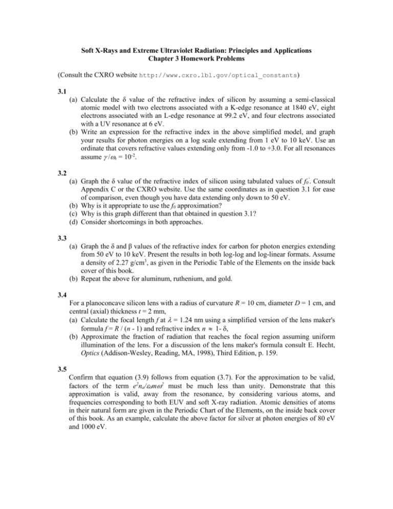
Soft X-Rays and Extreme Ultraviolet Radiation: Principles and Applications Chapter 3 Homework Problems (Consult the CXRO website http://www.cxro.lbl.gov/optical_constants) 3.1 (a) Calculate the δ value of the refractive index of silicon by assuming a semi-classical atomic model with two electrons associated with a K-edge resonance at 1840 eV, eight electrons associated with an L-edge resonance at 99.2 eV, and four electrons associated with a UV resonance at 6 eV. (b) Write an expression for the refractive index in the above simplified model, and graph your results for photon energies on a log scale extending from 1 eV to 10 keV. Use an ordinate that covers refractive values extending only from -1.0 to +3.0. For all resonances assume s = 10-2. 3.2 (a) Graph the δ value of the refractive index of silicon using tabulated values of f0'. Consult Appendix C or the CXRO website. Use the same coordinates as in question 3.1 for ease of comparison, even though you have data extending only down to 50 eV. (b) Why is it appropriate to use the f0 approximation? (c) Why is this graph different than that obtained in question 3.1? (d) Consider shortcomings in both approaches. 3.3 (a) Graph the δ and β values of the refractive index for carbon for photon energies extending from 50 eV to 10 keV. Present the results in both log-log and log-linear formats. Assume a density of 2.27 g/cm3, as given in the Periodic Table of the Elements on the inside back cover of this book. (b) Repeat the above for aluminum, ruthenium, and gold. 3.4 For a planoconcave silicon lens with a radius of curvature R = 10 cm, diameter D = 1 cm, and central (axial) thickness t = 2 mm, (a) Calculate the focal length f at = 1.24 nm using a simplified version of the lens maker's formula f = R / (n - 1) and refractive index n 1- , (b) Approximate the fraction of radiation that reaches the focal region assuming uniform illumination of the lens. For a discussion of the lens maker's formula consult E. Hecht, Optics (Addison-Wesley, Reading, MA, 1998), Third Edition, p. 159. 3.5 Confirm that equation (3.9) follows from equation (3.7). For the approximation to be valid, factors of the term e2na/0m2 must be much less than unity. Demonstrate that this approximation is valid, away from the resonance, by considering various atoms, and frequencies corresponding to both EUV and soft X-ray radiation. Atomic densities of atoms in their natural form are given in the Periodic Chart of the Elements, on the inside back cover of this book. As an example, calculate the above factor for silver at photon energies of 80 eV and 1000 eV. 3.6 (a) Discuss the physical significance of the phase velocity v = / k, and the group velocity vg = / k , for propagation of a transverse electromagnetic wave in a material of single electron atoms, each having a single resonance at = s. Assume s « 1, and an atomic density na. (b) Develop expressions for f0' and f0''. (c) Write an expression for the refractive index n in terms of , s, and p, where p2 = e2na /0m. (d) Neglecting for frequencies away from the resonance, write an expression for the dispersion relation between and k. (e) Using the expression obtained in part (c), discuss v for < s and > s. (f) Discuss vg for < s and > s in this same approximation. (g) Can vg exceed c in the immediate vicinity of the resonance (even with « 1)? Consult J.D. Jackson, Ref. 2 of this chapter. 3.7 Confirm that for H n 0 / 0 k 0 E , where n is complex, the average intensity can be written as in equation (3.20). Consult if necessary J. Stratton, and M. Born and E. Wolf, Refs. 3 and 1, respectively, of Chapter 3. 3.8 (a) Determine the complex refractive index of silicon for = 13.4 nm and for = 0.400 nm, in terms of and . Assume a density of 2.33 g/cm3. Use updated values from the CXRO website. (b) Calculate the absorption depth at both wavelengths. (c) What is the phase shift, relative to vacuum, of the wave propagating through a 100 nm thickness of silicon at these two wavelengths? (d) Calculate the critical angle for total external reflection at both wavelengths. 3.9 Calculate the critical angle for total external reflection from nickel ( = 8.91 g/cm3) and from gold ( = 19.3 g/cm3), for wavelengths of 13.4 nm (EUV), 2.50 nm (SXR), and 0.400 nm(Xray). 3.10 Calculate the normal incidence reflectivity at a vacuum-copper (Z = 29) interface for photon energies of 80 eV (EUV), 500 eV (SXR), and 8 keV (X-ray). 3.11 Calculate the reflectivity of ruthenium at photon energies of 100 eV, 1 keV, and 10 keV, for a glancing angle of incidence of 30 mrad. 3.12 (a) What is the normal incidence reflectivity for 13.4 nm radiation at a single vacuummolybdenum (Z = 42) surface? (b) What is it for a single silicon surface at normal incidence and this wavelength? (c) Make an educated guess as to how many Mo/Si interfaces would be required in a multilayer mirror to achieve a reflectance of approximately 40−60 %. Neglect absorption, approximate silicon by a vacuum (n = 1) spacer, assume the interface spacings permit positive interference of the reflections from all interfaces, and recall that the phase change upon reflection varies in sign depending on the sequence of high and low refractive index materials. (d) What is the required bi-layer periodicity (d-spacing) required for positive interference? Note that this problem will be considered computationally, including absorption, in Chapter 4. 3.13 (a) Calculate reflectivity versus photon energy for iridium (Z = 77) at 0.75° glancing incidence (45 arc min). Use scattering factors from the CXRO website. (b) How might a mirror of iridium be used in an x-ray telescope? 3.14 In designing a filter to transmit K characteristic emission from atoms of a single element (C, O, or Cu, etc.), while blocking other wavelengths, what is generally a good material to start with? Draw an energy diagram to explain your answer. 3.15 (a) For the case of p-polarized radiation in which the electric field is parallel to the plane of incidence, apply the appropriate boundary conditions to obtain an expression for the reflected electric field in terms of E0, n, and as given in equation (3.54). (b) From this derive the angle of minimum reflectance, known as Brewster's angle or the polarizing angle. (c) Give a physical description as to why one would expect little or no reflection of ppolarized radiation at this angle. (d) Why is there no Brewster's effect for s-polarized radiation? 3.16 (a) Calculate Brewster's angle for visible light incident from air on a glass surface assuming n = 1.5. (b) How can this be used to minimize cavity losses and control polarization of a laser? Consult the texts by Silfvast and by Siegman, Refs. 9 and 7 respectively in Chapter 7, for further discussion of Brewster's angle optics in lasers. 3.17 (a) Calculate Brewster's angle for 6.8 nm wavelength radiation incident from vacuum on a carbon mirror. (b) How should the surface be oriented to suppress horizontally polarized radiation while reflecting vertically polarized radiation? 3.18 (a) What is Brewster's angle for 14.0 nm wavelength radiation incident from vacuum on a silicon surface? What is Brewster's angle for nickel at a photon energy of 730 eV?
