Attachment38 - Engineering Projects India Ltd.
advertisement
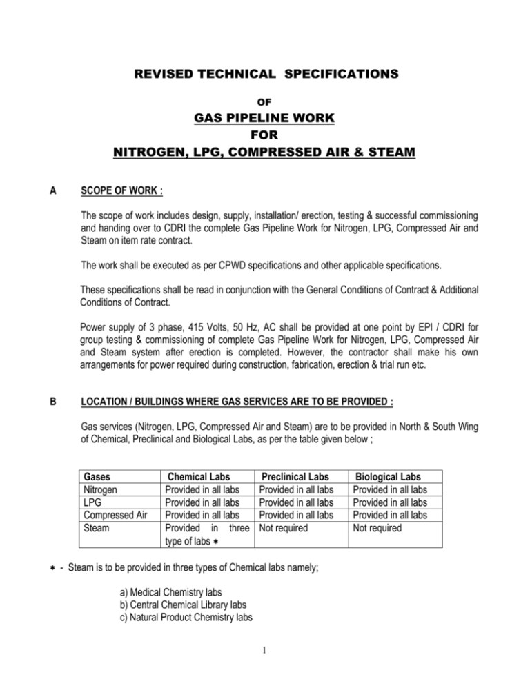
REVISED TECHNICAL SPECIFICATIONS OF GAS PIPELINE WORK FOR NITROGEN, LPG, COMPRESSED AIR & STEAM A SCOPE OF WORK : The scope of work includes design, supply, installation/ erection, testing & successful commissioning and handing over to CDRI the complete Gas Pipeline Work for Nitrogen, LPG, Compressed Air and Steam on item rate contract. The work shall be executed as per CPWD specifications and other applicable specifications. These specifications shall be read in conjunction with the General Conditions of Contract & Additional Conditions of Contract. Power supply of 3 phase, 415 Volts, 50 Hz, AC shall be provided at one point by EPI / CDRI for group testing & commissioning of complete Gas Pipeline Work for Nitrogen, LPG, Compressed Air and Steam system after erection is completed. However, the contractor shall make his own arrangements for power required during construction, fabrication, erection & trial run etc. B LOCATION / BUILDINGS WHERE GAS SERVICES ARE TO BE PROVIDED : Gas services (Nitrogen, LPG, Compressed Air and Steam) are to be provided in North & South Wing of Chemical, Preclinical and Biological Labs, as per the table given below ; Gases Nitrogen LPG Compressed Air Steam Chemical Labs Provided in all labs Provided in all labs Provided in all labs Provided in three type of labs Preclinical Labs Provided in all labs Provided in all labs Provided in all labs Not required - Steam is to be provided in three types of Chemical labs namely; a) Medical Chemistry labs b) Central Chemical Library labs c) Natural Product Chemistry labs 1 Biological Labs Provided in all labs Provided in all labs Provided in all labs Not required C BATTERY LIMITS : (a) Nitrogen & LPG From outlet of source (Nitrogen Cylinder Bank /LPG Cylinder Bank) located at one side of lab to final termination in each lab at four outlets. The scope also includes installation of Nitrogen Cylinder Bank & LPG Cylinder Bank . However, Nitrogen / LPG cylinders shall be provided by CDRI / EPI. (b) Compressed Air From outlet of source (Compressed Air) located in between North & South wing of lab to final termination in each labs at four outlets. The scope also includes installation of compressor (1 working + 1 Standby) with all accessories, for each type of labs. (c) Steam From outlet of source (Steam generator / Boiler) located near Chemical labs to final termination in only three types of Chemical labs ( namely Medical Chemistry labs, Central Chemical Library labs and Natural Product Chemistry labs ) at four outlets. However, the source i.e. Steam generator / Boiler for Steam shall be in the scope of other contractor. 2 1.0 TECHNICAL SPECIFICATION FOR PIPING WORK : 1.1 This specification governs the requirements for design, manufacture, fabrication, erection, testing, cleaning & commissioning of the piping work. 2.0 SERVICE GAS : 2.1 Gaseous Nitrogen, Air, LPG & Steam 3.0 SCOPE OF WORK BY CONTRACTOR : 3.1 Generally, the scope of work of contractor shall include the following without being limited to the same. Scope of supply of various materials for fabrication and erection shall be as per details given in special conditions of contract. 3.2 Supply of piping materials to work site/shop, fabrication and erection of all piping system in accordance with this specification, enclosed specifications for pipes, valves, painting, etc. applicable drawings and standards and also necessary modifications which shall come during erection. 3.3 Fabrication and erection of pipe supports, supporting fixtures, brackets,. as per pipe support standards and drawings and instructions of Engineer-in-Charge. 3.4 Underground piping including covering materials, excavation and backfilling. Anchor Block/insert lock, supports, and pedestal (concrete) pipe sleepers. 3.5 The contractor shall also bear the cost of repair, changes, replacement, etc. due to noncompliance with the standards, codes or due to disregard of instructions given by Engineer-in-Charge. 3.6 A) Dye - penetrant test for All 100 % of the total no. of joints, etc. as required by Engineer In Charge. B) Radiography shall be 10 % of all Butt Welding Joints are must. 3.6 Flushing, cleaning and testing of all piping system. 3.7 Providing two coats of red oxide zinc chromate primer and oil painting on all MS/CS pipes/structural supports, etc. 3.8 Acid pickling of SS welds in pipes/plates etc. wherever applicable. 3.9 Any other items as required in the drawings/specifications to be fabricated and erected from pipe/plate materials. 3 4.0 Erection of Valves : 4.1 Supply & Erection of all types of valves such as globe, ball etc. 5.0 FABRICATION OF SUPPORTS: 5.1 Fabrication of all types of pipe supports, provided as per the instructions of the Engineer-in-Charge, will be paid on weight basis. Materials for fabrication of support will be supplied by Contractor. Bolts, nuts & washers will be supplied by Contractor. 6.0 BASIS OF WORK, CODES & STANDARDS : 6.1 The complete piping work shall be carried out in accordance with Approved Drawings and standards and any drawings/ documents prepared by contractor and duly approved by Engineer-inCharge/Owner. 6.2 Approved for Construction" drawing and sketches issued by EPIL to contractor such as Piping and equipment layout plans. 7.0 SPECIFICATIONS : 7.1 Welding Procedure/Qualification : ASME B 31.3/31.8, ASME Sec IX & IS: 817 7.2 ASME Sec IX & IS: 814 : Material Specifications, Welding rods, Electrodes & filler wire etc. 7.3 ANSI-B-16.5 : Pipe Flanges & Flanged Fittings 7.4 ASME/ANSI-B-16.10 : Face-to-Face & End-to-End Dimensions of Valves 7.5 ASME/ANSI-B-16.21 : Non-metallic Flat Gaskets for Pipe Flanges. 7.6 ANSI-B-18.2.1 : Square & Hex Bolts & Screw. 7.7 ANSI-B-18.2 : Stud & Nuts. 7.8 ASTM A 312 TP 304/316, Seamless, ANSI B36.19 : Pipes. 7.9 ASTM A 312 TP 304/316/ ANSI B 36.19 : Pipe Fittings 8.0 IS Standard or Equivalent Gauges : 4 : 8.0 SPECIFICATIONS FOR PIPE JOINTS : PIPE JOINTS 8.1 In general joints shall be butt welded as specified in the applicable valve & piping specifications, with flanges and butt weld fittings used on where required. 8.2 Fabricated piping system shall be erected as detailed on piping layout drawing and as advised by the Engineer-in-Charge. The contractor shall provide adequate field joints bearing in mind the fact that there may be variations in locations of equipments, equipment nozzles, inserts, structures, etc. but not limited to the aforesaid contingencies only. In certain cases site measurement may have to be taken before commencement of fabrication. 8.3 Flange joints shall be used at connections to vessels, equipments, valves, flanged fittings and wherever required for ease of erection and maintenance as indicated in the drawings. 9.0 EDGE PREPARATION : 9.1 The edges to be welded shall be prepared to meet the joint design requirements by any of the following methods. For Stainless Steel 9.2 Plasma cutting, machining or grinding methods shall be used. After plasma cutting, cut shall be machined or ground smooth. 9.3 The edges prepared shall be as per ANSI-B-31.3. 9.4 The ends to be welded shall be properly cleaned to remove paint, oil, grease, rust, oxides, sand, earth or any other foreign material. The ends shall be completely dry before welding commences. 10.0 WELDING : 10.1 Welding of butt joints/socket weld joints, etc. has been broadly described in the "Welding Specification”. 10.2 For stainless steel, welding shall be done using inert Argon gas shielded Tungsten Arc process and Dry Nitrogen as for purging. 11.0 STRUCTURE STEEL : 11.1 The work covered consists of fabrication and erection of structural steel pipe supports in strict accordance with specification and applicable drawings. 5 12.0 WELDING SPECIFICATION: 12.1 All welding shall have full thickness penetration and shall be done by the TIG process. Tack welds lacking penetration shall be chipped out completely and re-welded properly. 12.2 In multiple pass welding, each layer shall be cleaned of all stag, scale and other foreign matter and any serious defects chipped out before subsequent welding is done. Next run of weld shall be carried out only after thorough inspection, rectification and preparation of the previous run. Use stainless steel chipping tools and wire brushes for cleaning. 12.3 The completed weld shall be cleaned of slag and spatter if any. 12.4 No under cutting of pipe adjacent to the completed weld will be permitted. 12.5 Pipes shall be brushed with stainless steel wire brushes and then cleaned for a distance of at least 50mm from the weld area. Filler material shall also be cleaned in similar manner. 12.6 In order to get optimum benefit, carbide precipitation has to be avoided. Also it is essential to retain the high strength resulting from cold works. It is therefore, extremely important to control the temperature and duration of welding very effectively. By using purging and trailing gas of TIG welding and large current for extremely short periods of time in MMA welding, the desired optimum results may be achieved. 12.7 Root pass shall be made with electrodes/filler wires recommended in the welding specification chart. The preferable size of the electrode is 2.5 mm diameter (12 SWG) but in any case not greater than 3.25 mm (10 SWG) 12.8 The root run of butt joints should be executed properly so as to achieve full penetration with complete fusion of the root edges. Weld projection inside the pipes shall not exceed 3mm, wherever not specified by the applicable code. All root run will be done by TIG welding for Butt Joints. 12.9 While welding is in progress, care should be taken to avoid any kind of movement of the components, shocks, vibrations and stresses to prevent occurrence of weld cracks. 12.10 Wherever grinding wheels are required for grinding purpose, for stainless steel suitable type of grinding wheels shall be used. Separate grinding wheels and wire brushes should be used for carbon steels and stainless steels. 12.11 Welding shall be free from undercuts and other defects. 12.12 Each weld joint should have workmen like finish. 6 13.0 ELECTRODES & FILLER WIRES : 13.1 Welding electrodes with a suitable coating/filler wires shall be in accordance with IS:814/ASME Sec. ll, latest edition and of a recognised quality. These shall be approved by Engineer-in- Charge before being used in the work. Approved makes are to be used. The contractor shall submit batch test certificate from the electrode manufacturer. The following specifications of electrodes are recommended for welding: 13.2 General structural welding : AWS-E-6012 13.3 Carbon Steel : AWS-E-6018/7018 13.4 Carbon Steel to stainless steel : AWS-E-310/309 13.5 Stainless Steel filler wire -AISI 304/316 : 13.6 All electrodes shall be purchased in sealed containers and stored properly to prevent deterioration. The electrodes removed from the containers shall be kept in holding ovens at temperatures and time recommended by the electrode manufacturer. Out of the oven, time of electrodes before they are consumed, shall not exceed the limits recommended by the electrode manufacturer. The electrodes shall be handled with care to avoid any damage to the flux covering. A 121 14.00 TESTING AND COMMISSIONING : 14.1 Hydraulic Testing : All piping shall be hydrostatically tested for 1.5 times of working pressure after completion of fabrication. 14.2 Pneumatic Testing : All piping shall be pneumatically tested for the specified pressure where called of. After successful commissioning of the pipelines, the contractor shall conduct performance tests on the equipment to satisfy the engineer that all the equipment perform to the rated outputs. Equipment like valves, fittings etc. shall be replaced (not repaired) if the same is not giving rated output. 15.0 LAYING & PROTECTION OF BURRIED PIPING : 15.1 No primer paint is required. 15.2 Three coats of cold coal tar (SHALIMASTIC H.D. or equal) shall be applied resulting in a final film thickness of 0.79 mm. simultaneously in inner-wrap of Fibre glass reinforced or equal shall be pulled into it. Manufacturer's recommendation shall be followed for the coat tar application. 7 15.3 Immediately following the application of the inner-wrap a layer of outer-wrap (Fibre glass based impregnated with coat tar or equal) shall be applied to the external surface of the coating. 15.4 The coating shall then be allowed to dry and shall be protection from burrs, scratches and sharp edges. 16.0 PIPING LAYOUT : 16.1 The route given is tentative and may change with execution quantities as actually executed shall be measured at site and paid accordingly. 17.0 COLOUR CODE FOR PIPING : 17.1 The colour code scheme is identified for identification of the individual service of the pipeline. LPG Nitrogen Air Steam : : : : Red WHITE French Gray Yellow 18.0 SITE VISIT & DRAWING PREPERATION : 18.1 The vendor may desire to make a visit to the site to take exact measurement at site prior to Quoting of the subject work would be allowed do so with prior information to this office. successful vendor. 19.0 DEVIATION : 19.1 Vendors are required to quote for the material as per the technical specifications and work as mentioned in the Tender. Deviations to the specifications of any must be brought out clearly giving a deviation statement. 20.0 WARANTEE PERIOD : 20.1 Warrantee Period: 12 months from the date of Commissioning and vendor shall rectify/replace if any defect developed within the period, free of cost. In any circum stances no additional charge will be paid on any account i.e. Transportation/ Mobiliasation / Lodging /Boarding etc. 8 21. TECHNICAL SPECIFICATIONS OF PIPE,PIPE FITTINGS AND VALVES : A) Stainless Steel Pipes : Material Material of Construction Standard Dimensional Standard Length Sizes Make/Supplier : : : : : : : B)Stainless Steel Pipe Fittings: Material Material of Construction Type Dimensional Standard Sizes Make/Supplier : : : : : : SS Piping, Seamless SS 304 as per ASTM A 312 TP 304, Seamless. ANSI B 36.19 4-6 Mtrs Length 40 NB/ 25 NB/15 NB, Sch 40 Reputed Indian Manufactures Ratanmani, Remi or Equivalent Imported Make like Sumitomo. Pipe Fittings as per ASTM A 312 TP 304 Socket Weld/ Butt Weld ANSI B 36.19 40 NB/ 25 NB/15 NB, Sch 40 Bharat Forge/Fitwell/ Sanghi Impex/ Swastik Engg/ Navkar C) Nitrogen Manifold System and Piping Components : Nitrogen Manifold system shall consits all components shown in drawing and makes and specification as per below. System complete in all respect from Design to use with Hyd and Pneumatic Test Certificates and all OEM test certificates for brought out items. 1) M. S. fabricated support framework for in Cylinders and Manifolds etc: The cylinders will be fitted to M.S. fabricated support framework fabricated using ISMC 75 x40, ISA 65X65X5. Framework shall be designed to hold 20 nos. 47 /50 Ltrs. W.C. cylinders. The framework shall be of knockdown type, assembled using M.S. fasteners. It shall be freestanding, floor-mounted type with footplates fixed to the floor by anchor bolts and painted Black Colour. Frame will also consist of Chain to hold cylinder firmly. Construction Finish Material Used : : ; Arc Welding and Bolting. One Coat of Primer & two Coates Synthetic enamel Paint. MS. Channel /Angle/ Plate as per IS : 808/1730 / 1731 Gas Service Working Pressure Hyd. Test Pressure Operating Temp. MOC : : : : : Construction : Nitrogen 150 Bars 225 Bars 50 Degree C Pipe: SS 304, 1” NB, SCH 80 Seamless Pipes as per ANSI B 36.19 Fittings from SS 304 Bar stock./ Machined as per requirement TIG Welding for Header, Tee pieces Elbows, Cross Pieces etc. 2)Manifold Header: 9 Testing Type Welding Code : : : Hydraulic & Pneumatic Testing 10 x 2 Cylinders . ASME B 31.3/ 31.8 : : : : : SS outer core and PTFE inner core as per SAE 10 R 14 200 Bars. 300 Bars. ¼” size, 1000 mm long. Powerflex Industries, Insap, Composite Hoses Mumbai : : : : : : Needle type Vanaz Engineers , Pune , / MUPL , Bangalore Brass 1 “size. 200 Bars. As per BS/IS Standard 3) Flexible Hose : Material of construction Working Pressure Hydraulic Test Pressure Size Make 4) Branch Isolation Valves : Type Make Material of construction Size Working Pressure Standard 5) Manifold Port Isolation Valve:` Type : Make : Material of construction : Size : Working Pressure : Needle type Vanaz / Batra/Tecno make as per IS 3224 Brass As per Standard. 150 Bars. 6) Pressure Gauge: Make Type Dial size Range AccuracyBourdon tube Thread Mounting Connections Housing Pointer Standard : : : : : : : : : : : : WIKA Gauges Bourdon, Waree Instruments or Equivalent Bourdon tube Pressure gauge 100 MM 0 to 280, 0-16 kg/cm2 1:1% of full-scale division SS 316 ½” NPT/ B.S.P (Male) Direct Mounting Bottom connection Weather proof housing Micro type adjustable pointer Indian Or European or equivalent Standard 7) Pressure Gauge and Vent Type Make Material of construction Size Working Pressure Isolation Valve: : Needle type : Vanaz / Batra/Tecno make as per IS 3224 : Brass : As per Standard. : 150 Bars. 10 8) Pressure Regulator: Make Type Body and Cap Diaphragm and Internal Trim Inlet Pressure Outlet pressure Gas Service Flow Rate Inlet connections Outlet / inlet connections Standard : : : : : : : : : : : Vanaz Engineers, Nirmal Industries, CIE, VKE Valves Single Stage Brass as per Manufactures standard/ Rubber 0 to 150 Bars. 0.3 to 10 Bars Nitrogen. 300 NM3 / Hr. 1 “ BSP 1” BSP As per Manufactures Standard. D) LPG Manifold System and Piping Components : LPG Manifold system shall consits all components shown in drawing and makes and specification as per below. System complete in all respect from Design to use with Hyd and Pneumatic Test Certificates and all OEM test certificates for brought out items. 1)M.S. fabricated support framework for in Cylinders and Manifolds etc: The cylinders will be fitted to M.S. fabricated support framework fabricated using ISMC 75 x 40, ISA 65X65X5. Framework shall be designed to hold 20 nos. 47 /50 Ltrs. W.C. cylinders. The framework shall be of knockdown type, assembled using M.S. fasteners. It shall be freestanding, floor-mounted type with footplates fixed to the floor by anchor bolts and painted Black Colour. Frame will also consist of Chain to hold cylinder firmly. Construction : Arc Welding and Bolting. Finish : One Coat of Primer & two Coates Synthetic enamel Paint. Material Used ; MS. Channel /Angle/ Plate as per IS : 808/1730 / 1731 2)Manifold Header: Gas Service Working Pressure Hyd. Test Pressure Operating Temp. MOC : : : : : Construction Testing Type Welding Code : : : : LPG 10.50 Bars 15.75 Bars 50 Degree C Pipe: SS 304, 1.5” NB, SCH 40 Seamless Pipes as per ANSI B 36.19 Fittings from SS 304 Bar stock./ Machined as per requirement TIG Welding for Header, Tee pieces Elbows, Cross Pieces etc. Hydraulic & Pneumatic Testing 10 x 2 Cylinders. ASME B 31.3/ 31.8 3)Flexible Hose: Make Material of construction Working Pressure Size Length : : : : : COMAP/ Surksha- HP/ United works as per Is standard Nylon Braided Hose 10 Bars. ¼” size. 3 Feet long. 11 Port Isolation Valve for Manifold : Make : Material : Size : Type : Working Pressure : COMAP/ Vanaz/ United Works , Messers Brass 3/8 “ BSP or as required Needle / Ball Type 10.5 Bars Main and Manifold Isolation Valve for Manifold : Make : COMAP/Shenco / United Works, Messers Material : Brass Size : 3/8 “ BSP or as required Type : Ball Working Pressure : 10.5 Bars Pressure Gauge: Make Type Dial size Range AccuracyBourdon tube Thread Mounting Connections Housing Pointer Standard : : : : : : : : : : : : Forbes Marshall, WIKA, Waree Instruments, Gauge Bourdon Bourdon tube Pressure gauge 100 MM 0 to 280, 0-16 kg/cm2 1:1% of full-scale division SS 316 ½” NPT/ B.S.P (Male) Direct Mounting Bottom connection Weather proof housing Micro type adjustable pointer Indian Or European or equivalent Standard Pressure Gauge and Vent Isolation Valve: Type : Needle type Make : COMAP/ Vanaz/ United Works Vanaz , Messers Material of construction : Brass Size : As per Standard. Working Pressure : 10.5 Bars. Pressure Regulator: Make Type Body and Cap Diaphragm and Internal Trim Inlet Pressure Outlet pressure Gas Service Flow Rate Inlet connections Outlet / inlet connections Standard : : : : : : : : : : : COMAP/ Vanaz/ Nirmal Industries . United Works , Messer Single Stage Brass as per Manufactures standard/ Rubber 0 to 10.5 Bars. 0.3 to 10 Bars LPG 200 NM3 / Hr. 1 “ BSP Or as required 1 “ BSP Or as required As per Manufactures Standard. 12 E) Outlet Isolation Valve Low Pressure : Service Type Make : : : Material of construction Size Op. pressure Operating Temperature Design & Type End to End Dimensions Type of Operation : : : : : : : LPG Ball Valve COMAP/ Vanaz/ United Works , Messer SHENCO / GG Valves / BDK VALVES/AUDCO SS 304/Brass 1.5 “/1/2 “ , 1 “ 21 Kg /cm2 50° C BS 5351 & Two/Three piece Construction As per ASME B 16.10 Manual, Plastic Coated Hand lever F) Inside Lab LPG Pressure Regulators : Make Type Body and Cap Diaphragm and Internal Trim Inlet Pressure Outlet pressure Gas Service Inlet connections Outlet / inlet connections : : : : : : : : : COMAP/ Vanaz/ NirmaI Industries/ United Works , Messers Single Stage Brass / Al Brass/ Al 0 to 1o.5 Bars. 0.3 to 10 Bars LPG ½ “ NPT F ½ “OD Tube G) Outlet Isolation Valve Low Pressure : Service Type Make Material of construction Size Op. pressure Operating Temperature Design & Type MOC : : : : : : : : : Body Test Pressure – Hydraulic : End to End Dimensions : Type of Operation : Nitrogen/ Compressed Air Ball Valve SHENCO / GG Valves / BDK VALVES/AUDCO SS 303 1.5 “ 21 Kg /cm2 50° C BS 5351 & Two/Three piece Construction Body ASTM A 351Gr. CF 8 Ball AlSI 304 Bore Type - Full Bore Stem - AlSI304 Gland - AlSI304 Seat Virgin - PTFE Seal Packing - Virgin PTFE Bolts, Nuts & Studs ASTM A 193 Gr. B ASTM A 194 Gr. 2 H 31,Kg/ cm2 As per ASME B 16.10 Manual, Plastic Coated Hand lever 13 H) Safety Relief Valve : Type Gas Service Set Pressure Make Material of construction Size Working Pressure Standard : : : : : : : : Relief Valve Compressed Air, Nitrogen 11 Bars ( Adjustable) CIE , Mumbai/ Nirmal Industries- Mumbai/ Flinger - Ahamdabad C.S. 1 “ or as required capacity . 15 Bars API Standard . I) Room / Line Isolation Ball Valve OR Outlet Isolation Valve Low Pressure : Service Type Make Material of construction Size Op. pressure Operating Temperature Design & Type MOC : : : : : : : : : Body Test Pressure – Hydraulic : End to End Dimensions : Type of Operation : J) SS Pressure Regulators Nitrogen and Compressed Air Ball Valve SHENCO / GG Valves / BDK VALVES/AUDCO SS 304 1.0 “/ ½ and 1.5 “ 21 Kg /cm2 50° C BS 5351 & Two/Three piece Construction Body ASTM A 351Gr. CF 8 Ball AISI 304 Bore Type - Full Bore Stem - AlSI304 Gland - AlSI304 Seat Virgin - PTFE Seal Packing - Virgin PTFE Bolts, Nuts & Studs ASTM A 193 Gr. B ASTM A 194 Gr. 2 H 31 Kg/ cm2 As per ASME B 16.10 Manual, Plastic Coated Hand lever. : Make : Type Body and Cap Diaphragm and Internal Trim Inlet Pressure Outlet pressure Gas Service Inlet connections Outlet / inlet connections Flow Rate : : : : : : : : : C. P. Engg Works, Thane, Nirmal Industries / BOC India / Praxair India Pvt. Ltd. Single Stage SS 304/316 SS 304/316 0 to 150 Bars. 0.3 to 10 Bars Nitrogen. ½ “ NPT F ½ “OD Tube 100 LPM at 4.0 bars. 14 K) Compressed Air Pressure Reducing Station: This pressure reducing station consits of 1.5 “ size Inlet , Outlet Isolation Ball Valves, 2 Nos 300 M3 / Hr rating flow rate Regulators , Brass Body Regulators , Safety Relief Valves etc. Pressure Reducing and By Pass System/ Station have following specification. Gas Service Working Pressure Hydro test Pressure Regulators : : : : Ball Valves : Pressure Gauges : Pipes and Pipe fittings : Safety Relief Valve : Mounting : Reference Documentation : : Compressed Air 10.5 Bars 15 Bars Brass Body, 1.5” size, High Flow, Single Stage Make : Vanaz Engineers, Nirmal Industries, CIE, VKE Valves SS, 1.5 “, Full Bore except PG Isolation valve ½ “ size Make : SHENCO / GG Valves /BDK VALVES/AUDCO Complete SS, 4 “ Dial, 0-16 Bars, Make : Forbes Marshall, WIKA, Waree Instruments, Gauge Bourdon As per ASME / STM Standard of required 1.5 “ , Sch 40 size Set Pressure 11 Bars ( Adjustable), C.S. 1” size, As per API Standard Make : CIE, Mumbai/ Nirmal Industries- Mumbai/ Flinger – Ahmadabad. All components shall be mounted on M.S. Fabricated structure either wall or Floor Mounted. Drawing Enclosed. All OEM and Hyd Test Certificates along with supply. L) S.S Tubing : Material Size Gas Service Working Pressure : : : : SS 304/ SS 316 as per ASTM A269 TP 304/316 1/2” OD, 1mm TO 1.2 mm thick, Seamless, 6 Mtrs. straight in length SS 304 for Air, N2, LPG and for Steam SS 316 50 Bars. M) S.S Tube Fittings and SS ball Valve (Point Of Use): Make Type Material Gas Service Working Pressure : : : : : Prime Engineers / Excel Hydro, Equivalent. Fittings with double compression ferrules and nuts. SS 316/304 H2, Air, N2, O2, Argon, Helium,C2H2, N2O etc 50 Bars 15 N) Steam Service Components : For Steam Piping Pressure is max 21 Bars and Temp. is 200 o C. All piping material and Components are ss 316 make only or as per specified in tech Bids etc. Pressure Reducing Station : Pressure Rating Outlet Pressure Material Of Construction Size MOC Pressure and Temp Inlet Connection Inlet Connection Accessories Make : : : : : : : : : : 21 Bars 0 -15 Bars SS 316 40NB/25NB/15 NB SS 316/316L Max. 21 Bars/ Max 2000 C As per system / Piping Requirement. As per system / Piping Requirement. Ball Valves / Piping / Temp and Gauges of SS 316 MOC Uni Klinger Ltd. , Pembril Engineering Pvt. Ltd , Varall Engineers, Dee Greaves Ltd. , Pennant Engg, Pune, Forbes Marshall (Spirex), Jordon or Alfa Lavel approved or equivalent make Ball Valves / Steam Trap / Strainers : Pressure Rating Material Of Construction Size MOC Pressure and Temp Inlet Connection Inlet Connection Make : : : : : : : : Compact Steam Trap Assembly : 21 Bars SS 316 40NB/25NB/15 NB SS 316/316L Max. 21 Bars/ Max 2000 C As per system / Piping Requirement. As per system / Piping Requirement. Uni Klinger Ltd. , Pembril Engineering Pvt. Ltd , Varall Engineers, Dee Greaves Ltd. , Pennant Engg, Pune, Forbes Marshall (Spirex), Jordon or Alfa Laval approved or equivalent make Steam Trap assembly consits of inbuilt Strainer, inlet, outlet, Check Vent valves etc,. and other standard accessories etc Pressure Rating Material Of Construction Size MOC Pressure and Temp Inlet Connection Inlet Connection : : : : : : : 21 Bars SS 316 40NB/25NB/15 NB CS ASTM A 216 Gr. WPB Max. 21 Bars/ Max 2000 C As per system / Piping Requirement. As per system / Piping Requirement. 16 Make : Uni Klinger Ltd. , Pembril Engineering Pvt. Ltd , Varall Engineers, Dee Greaves Ltd. , Pennant Engg, Pune, Forbes Marshall (Spirex), Jordon or Alfa Laval approved or equivalent make Pressure Regulator ( at Point Of Use) : Pressure Rating Outlet Pressure Material Of Construction Size MOC Pressure and Temp Inlet Connection Inlet Connection Make : : : : : : : : : 0-15 Bars 0 - 12 Bars SS 316 15 NB SS 316/316L Max. 21 Bars/ Max 2000 C As per system / Piping Requirement. As per system / Piping Requirement. Uni Klinger Ltd. , Pembril Engineering Pvt. Ltd , Varall Engineers, Dee Greaves Ltd. , Pennant Engg, Pune, Forbes Marshall (Spirex), Jordon or Alfa Lavel approved or equivalent make : : SS 316 WIKA, Waree Forbes Marshall( Spirex), Jordon or Alfa Level approved or equivalent make Temp and Pressure Gauges : Material Of Construction Make 17 Air Compressor : Compressor Make Pressure Flow Acceserier : : : : : Receiver Tank Make : : 0.5 M3 . (500 Ltrs) of 14 Bars working pressure As per IS Standard make and reputed supplier like IR/ Kaeser / Boge/ Ewata /Atlas Copco/ Savair Heatless Dryer : Make : Dryer includes all required accessories including fliters for Paper, Borosilicate, Activated Carbon filter etc of rated capacity. As per Standard make and reputed supplier MTA Italy, Sabro, Dominick Hunter, Savair , Trident etc IR/ Kaeser / Boge/ Ewata /Atlas Copco/ equivalent 10 Bars 40 CFM Complete with all asscceries WORKING PRESSURE OF PIPELINE 22 SL.NO SERVICE 1 2 3 4 Nitrogen Compressed Air LPG Steam WORKING PRESSURE 10 kg/cm2 10 kg/cm2 10 kg/cm2 21 Kg/ Cm2 HYDRAULIC TEST PRESSURE 15 kg/cm2 15 kg/cm2 15 kg/cm2 33 Kg/cm2 RUNNING-IN-PERIOD After satisfactory final inspection as stated the contractor shall demonstrate the trouble free running of the installation for a period of not less than 10 days before CDRI takes over. The duty cycle of the plant/system during this Running-In-Period shall be 10-12 Hours. After the installation has operated for 10 days period without any breakdown or abnormal / unsatisfactory operation of during this period, the Gas Pipeline Work for Nitrogen, LPG, Compressed Air and Steam system shall be deemed to have run trouble-free. The contractor should include one year of free running maintenance after completion of 10 days of trouble free running including replacement of defective parts etc. at his own cost. The contractor shall arrange at his own cost for all staff, fuel, POL, and other consumables during Trial run, Commissioning and Running-in-Period upto the date of acceptance. Nothing extra shall be paid on this account. 23 EFECTS LIABILITY PERIOD a) The defects liability period shall be for 12 months and the same shall start from the date of handing over to CDRI after successful commissioning and completion of the work (which shall be the day from which the gas pipeline system starts proper functioning). During this defects liability period, 18 the contractor shall ractify all the defects like leakages etc. The contractor shall also train the personnel as deputed by the CDRI, about the method of operation and maintenance of the gas pipeline work, its functioning and control. 24 GUARANTEES a) The guarantee shall cover each & every material whether manufactured by the contractor or not. The contractor shall replace the defective parts with new ones. Replaced parts shall also be covered by a similar guarantee. b) The replaced parts shall be of genuine make and subject to approval by the EPI / CDRI. c) The contractor shall guarantee the performance of the entire process, equipment and pipeline for a period of one year from the date of handing over to CDRI. 25 IDENTIFICATION OF PIPELINE FOR DIFFERENT GASES All different gas pipelines shall be color coded for identification as per applicable standards. A color band (strap) of 100 mm width shall be provided on pipe at a distance of 6 mtrs. 26 DOCUMENTS TO BE SUBMITTED 26.1 DOCUMENTS TO BE SUBMITTED ALONGWITH THE BID a) b) 26.2 Clear scope of work Complete BOQ DOCUMENTS TO BE SUBMITTED AFTER AWARD OF WORK a) System description, Detailed technical specifications of all Pipeline & Fittings, Operation & Control Philosophy, P&I diagram, General arrangement, Layout drawings of gas pipeline work. b) Contractor shall submit G.A. drawings, detailed working of cut-out and openings. c) Before commencing work, the Contractor shall prepare and submit all above drawings/documents etc. for Gas pipeline work in required nos. These drawings must be approved by the EPI/CDRI before execution of work and shall become part of the contract. d) The Contractor shall, within 3(three) weeks of receipt of a Letter of award of contract, submit 4(four) copies of all working drawings. e) Within 10 days of receipt of letter of award of contract, the Contractor shall obtain from the EPI/CDRI all the information he needs to prepare his design/drawings and shall have any interaction with the EPI/CDRI to finalise all parameters. The Contractor will be responsible for any discrepancies, errors and omissions in the drawings or particulars submitted by him even if these have been approved by the EPI/CDRI. 19 f) On approval of these drawings (within 2 weeks of submission of full documentation), the Contractor shall submit 8(eight) copies of approved working drawings incorporating corrections / comments, if any, and shall immediately commence work. g) On completion of work, the contractor shall supply four sets of CD’s and 8 (eight) copies of all Asbuilt drawings, catalogues, equipment operation & maintenance manuals and spare parts list at the time of handing over of the plants. h) The Contractor shall carry out all the work strictly in accordance with drawings, details and instructions of EPI/CDRI. 20 27 LIST OF TENDER DRAWINGS SR. NO. 1 2 3 4 5 6 7 8 9 10 11 12 13 14 15 16 17 18 19 20 DESCRIPTION DRG. No. P & ID FOR PRE CLINICAL LABORATORY GROUND FLOOR PLAN P & ID FOR PRE CLINICAL LABORATORY FIRST FLOOR PLAN P & ID FOR PRE CLINICAL LABORATORY SECOND FLOOR PLAN P & ID FOR BIOLOGICAL LABORATORY GROUND FLOOR PLAN P & ID FOR BIOLOGICAL LABORATORY FIRST FLOOR PLAN P & ID FOR BIOLOGICAL LABORATORY SECOND FLOOR PLAN P & ID FOR CHEMICAL LABORATORY GROUND FLOOR PLAN P & ID FOR CHEMICAL LABORATORY FIRST FLOOR PLAN P & ID FOR CHEMICAL LABORATORY SECOND FLOOR PLAN PRE-CLINICAL LABORATORY (1a) NORTH WING GROUND FLOOR PLAN PRE-CLINICAL LABORATORY (1a) SOUTH WING GROUND FLOOR PLAN PRE-CLINICAL LABORATORY (1a) NORTH WING FIRST FLOOR PLAN PRE-CLINICAL LABORATORY (1a) SOUTH WING FIRST FLOOR PLAN PRE-CLINICAL LABORATORY (1a) NORTH WING SECOND FLOOR PLAN PRE-CLINICAL LABORATORY (1a) SOUTH WING SECOND FLOOR PLAN BIOLOGICAL LABORATORY (1c) NORTH WING GROUND FLOOR PLAN BIOLOGICAL LABORATORY (1cS) SOUTH WING GROUND FLOOR PLAN BIOLOGICAL LABORATORY (1c) NORTH WING FIRST FLOOR PLAN BIOLOGICAL LABORATORY (1cS) SOUTH WING FIRST FLOOR PLAN BIOLOGICAL LABORATORY (1c) NORTH WING SECOND FLOOR PLAN 21 CDRI/LKW/PID/01 CDRI/LKW/PID/02 CDRI/LKW/PID/03 CDRI/LKW/PID/04 CDRI/LKW/PID/05 CDRI/LKW/PID/06 CDRI/LKW/PID/07 CDRI/LKW/PID/08 CDRI/LKW/PID/09 CDRI/LKW/499/All(A)-001aN CDRI/LKW/499/All(A)-001aS CDRI/LKW/499/All(A)-002aN CDRI/LKW/499/All(A)-002aS CDRI/LKW/499/All(A)-003aN CDRI/LKW/499/All(A)-003aS CDRI/LKW/499/All(A)-004cN CDRI/LKW/499/All(A)-004cS CDRI/LKW/499/All(A)-005cN CDRI/LKW/499/All(A)-005cS CDRI/LKW/499/All(A)-006cN SR. NO. 21 22 23 24 25 26 27 28 DESCRIPTION DRG. No. BIOLOGICAL LABORATORY (1cS) SOUTH WING SECOND FLOOR PLAN CHEMICAL LABORATORY (1bN) NORTH WING GROUND FLOOR PLAN CHEMICAL LABORATORY (1a) SOUTH WING GROUND FLOOR PLAN CHEMICAL LABORATORY (1bN) NORTH WING FIRST FLOOR PLAN CHEMICAL LABORATORY (1a) SOUTH WING FIRST FLOOR PLAN CHEMICAL LABORATORY (1bN) NORTH WING SECOND FLOOR PLAN CHEMICAL LABORATORY (1a) SOUTH WING SECOND FLOOR PLAN CHEMICAL LABORATORY (1bN) PIPING TYP SECTION FOR PIPING 22 CDRI/LKW/499/All(A)-006cS CDRI/LKW/499/All(A)-007bN CDRI/LKW/499/All(A)-007aS CDRI/LKW/499/All(A)-008bN CDRI/LKW/499/All(A)-008aS CDRI/LKW/499/All(A)-009bN CDRI/LKW/499/All(A)-009aS CDRI/LKW/499/All(A)-001-TD

