Coagulation & Flocculation: Water Treatment Design
advertisement
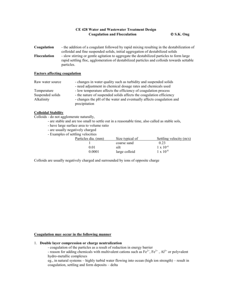
CE 428 Water and Wastewater Treatment Design Coagulation and Flocculation Coagulation Flocculation S.K. Ong - the addition of a coagulant followed by rapid mixing resulting in the destabilization of colloidal and fine suspended solids, initial aggregation of destabilized solids - slow stirring or gentle agitation to aggregate the destabilized particles to form large rapid settling floc, agglomeration of destabilized particles and colloids towards settable particles. Factors affecting coagulation Raw water source Temperature Suspended solids Alkalinity - changes in water quality such as turbidity and suspended solids - need adjustment in chemical dosage rates and chemicals used - low temperature affects the efficiency of coagulation process - the nature of suspended solids affects the coagulation efficiency - changes the pH of the water and eventually affects coagulation and precipitation Colloidal Stability Colloids - do not agglomerate naturally, - are stable and are too small to settle out in a reasonable time, also called as stable sols, - have large surface area to volume ratio - are usually negatively charged - Examples of settling velocities Particles dia. (mm) Size typical of Settling velocity (m/s) 1 coarse sand 0.23 0.01 silt 1 x 10⁻⁴ 0.0001 large colloid 1 x 10⁻⁸ Colloids are usually negatively charged and surrounded by ions of opposite charge Coagulation may occur in the following manner 1. Double layer compression or charge neutralization - coagulation of the particles as a result of reduction in energy barrier - reason for adding chemicals with multivalent cations such as Fe2+, Fe3+ , Al3+ or polyvalent hydro-metallic complexes eg., in natural systems – highly turbid water flowing into ocean (high ion strength) – result in coagulation, settling and form deposits – delta 2. Enmeshment of particles - addition of coagulants result in production of precipitate, eg., Al(OH) 3 or Fe(OH)3, - concentrations of 2 or 3 orders of magnitude beyond the solubility of the metal are used - colloidal particles get caught in these precipitates as they are formed - “sweep floc” conditions 3. Interparticle bridging - use of polymers (cationic, anionic, nonionic high molecular weight polymers) - long chain polymers - segments of a polymer chain absorb on more than one particle thereby linking the particles Design of Rapid Mix and Slow Mix Tanks Rapid mix - need to rapidly disperse the coagulant - detention time usually less than 1 min but can be as high as 2 minutes - high turbulence is required - a measure of the extent of shearing and mixing within a tank is given by G – velocity gradient G can be visualized as being the measure of the relative velocity of 2 particles at a given distance apart eg., two particles moving 1 m/s relative to each other and at a distance 0.1 m apart will have a G of 1/0.1 = 10 s-1 A general equation which relates the power input needed for mixing: 1/ 2 where G P V P G V = velocity gradient (s-1) = power input (watts = Nm/s) = volume of mixing basin (m3) = viscosity (Ns/m2) Values for G and td___________________________________________________________________ td (s) 20 30 40 >40 G (s-1) 1,000 900 790 700 _________________________________________________________________________________ Use of mechanical mixers - impeller driven mixers are the most efficient devices - relationship relating power input and the diameter of impellers and speed is given by: P = N3 D5 (equation 5-9) Valid for turbulence mixing with Re = ND2/ > 10,000 Where P = Power (Nm/s) = power number or impeller constant = density of the liquid (kg/m3) N = rotational speed (rev/s) D = diameter of impeller Points to note – impeller diameter should be within 30 to 50% of the width of the tank, if not will move the water and will not get efficient mixing 2 Example: A square rapid mixing basin with a depth of water equal to 1.25 times the width is to be designed for a flow of 7570 m3/d. The velocity gradient is to be 790 s-1, the detention time is 40 s, the operating temperature is 10o C and the turbine shaft speed is 100 rpm. Determine: 1. 2. 3. The basin dimensions Power required. Select the motor needed for the impeller if the efficiency of the motor and gearbox is 70%. Assume motors come in sizes of 1, 2.5, 5 and 7.5 hp. 1 hp = 745.7 W or J/s. Impeller diameter if a vane-disk impeller with six flat blades (see Table 13.4) is employed and the tank has four vertical baffles (one on each tank) 1. Volume = 7570 m3/d x 1/(60x 24) (d/min) (min/60s) x 40s = 3.5 m3 Dimensions w x w x 1.25 w = 3.5 m3 w = 1.41 m use w = 1.45 m H = 1.25 x 1.45 = 1.81 m use H = 1.80 m Total Height = 1.8 m + free board (assume 0.6 m) = 2.4 m New volume = 1.45 x 1.45 x 1.8 = 3.785 m3 Detention time = 3.785/ (7570 x 60 x 60 x 24) = 43 s. ok 2. Power required P = G2V = (790)2 x 0.00131 x 3.785 = 3087 Nm/s (W) (1/s)2 x (Ns/m2) x (m3) Power of motor = 3087/(746 x 0.70) = 5.91 hp use a 7.5 hp motor (1 hp = 746 watts) 3. Impeller diameter P = N3 D5 P D 3 N 1/ 5 3087 = 3 6.30 x999 .7 x (100 / 60 ) = 0.64 m D/w = 0.64/1.45 = 0.44 or 44% 1/ 5 within 30 to 50% of the width (ok) 3 Slow Mix or Flocculation relies on turbulence or gentle mixing to promote collision and agglomeration of particles if too much mixing (high G values) - flocs will be sheared, usually use G = 10 to 60 s-1, detention time of 20 to 45 minutes, typical 30 minutes or use G t values from 104 to 105 advantages to vary the G values over the length of the basin high G == > low G reasons == > allows for formation of strong flocs high G throughout = > small and strong floc low G throughout => large and weak floc Tapered effect => strong and large floc same equation is used for mechanical mixers - propeller type, common to use paddle flocculators Equation used P = 1/2 CD Ap Vp3 Where P CD Ap Vp = power input (Nm/s - watts) = drag coefficient 1.8 for flat blade = area of paddle blades (m2) = density of water (kg/m3) = velocity of paddle (m/s) relative to water Or a more general equation is given by: 3 ro 2N P 1 C D b (1 k ) r 3dr 2 60 r 1 Note that the r3dr comes from the Vp = 2 N r /60, earlier equation has Vp3. k is a constant. Information 1. Area of paddle Ap should not exceed 40% of the total area encompassed by the paddle 2. Velocity of the paddle tip Vp is the velocity relative to the water and is about 75% of the actual paddle speed without stators 85% - 100% of the actual paddle speed with stators (in book equation accounted for by k = 0.25, 0 - 0.15 with stators) 3. Paddle velocity should be less than 1 m/s 4. Minimum distance of 0.3 m should be maintained between paddle tips and all other structure in the flocculation basin to prevent local areas of excessive velocity gradients 5. Depth of basin should not be > 5 m, water flow through velocity between 0.5 - 1.5 fpm. Example : Designing a Flocculator: A water treatment plant is being designed to process 50,000 m3/d of water. Jar testing and pilot-plant analysis indicate that an alum dosage of 40 mg/L with flocculation at a Gt value of 4.0 x 10⁴ produces optimal results at the expected water temperatures of 15 o C. Determine: (1) The monthly alum requirement (2) The flocculation basin dimensions if three cross-flow horizontal paddles are to used. The flocculator should be a maximum of 12 m wide and 5 m deep in order to connect appropriately with the settling basin. (3) The power requirement. (4) The paddle configuration. 1. Monthly alum requirement 4 40 mg/L x (1kg /106 mg) x (103 L/m3) X 50,000 m3/d x (30d/month) = _________________ kg/month 2. Basin dimension (a) Assume an average G value of ____________ s-1. Then Gt = 4 x 10⁴ t = 4 x 10⁴ /30 x (1 min/60 s) = _____________ min. (b) Volume of tank is V = Qt = 50,000 (m3/d) X 22.22 min x (1d/1440 min) = __________________ m3 (c) The tank will contain three cross-flow paddles so it length will be divided into three compartments. For equal distribution of velocity gradients, the end area of each compartment should be square, i.e., depth equals 1/3 length. Assuming maximum depth of 5 m, length is 3 x 5 = _____________ m width is 5 x 15 x W = 771.5 W = _____________ m. (d) The configuration of the tanks and paddles should be as follows: 3. Power requirements: (a) Assume G value tapered as follows: First compartment, G = ____________ s-1 Second Compartment, G = ____________ s-1 Third compartment, G = ____________ s-1 (b) Power requirement for compartment 1, 2 and 3 P = G2 V Where V = 771.5 m3/ 3 = _____________ m3 At 15o C = 1.139 x 10⁻³ Ns/m2 P1 = (40)2 (1/s2) x 257.2 m3 x 1.139 x 10-3 Ns/m2 = _____ W = _______ kW P2 = (30)2 (1/s2) x 257.2 m3 x 1.139 x 10-3 Ns/m2 = _____ W = _______ kW 5 P3 = (20)2 (1/s2) x 257.2 m3 x 1.139 x 10-3 Ns/m2 = _____ W = _______ kW 4. Paddle configuration (a) Assume paddle design as shown below: Each paddle has four boards 2.5 m long and w wide. Three paddle wheels per compartment (b) Calculate w from power input and paddle velocity P At 15o C, C D A p v 3p 2 = 999.1 kg/m3 assume actual paddle speed = _________ m/s and CD = _____ Then vp = 0.67 x _________ = _________m/s Ap = length of boards x w x number of boards 3 paddles at __________ boards per paddle = ___________ boards 12 boards x 2.5 m (length) x w = 30 w = Ap P1 ___________ ___________ w = (468.7 N m/s) = 1.8 x 30w x 999.1 x 0.5 3)/2 = 1.8 x 30 x 999.1 x 0.53 w = 674.4 w = __________ m Calculate rotational speed of paddles = D = 4.2 = ___________ rev/min First compartment vp Second Compartment _______ Nm/s 260 vp Actual speed Rotational speed = 1.8 x (30 x 0.14) x 999.1 x vp3/2 = 3777 Ns2/m x vp3 = _____________ m/s = 0.41 / 0.75 = _____________ m/s = ______________ rev/min Third Compartment ________ Nm/s _________ vp Actual speed Rotational speed = 1.8 x (30 x 0.14) 999.1 x vp3/2 = 3777 Ns2/m x vp3 = ______________ m/s = 0.32 / 0.75 = ___________ m/s = ____________ rev/min 6 = ____________ m/s
