A.4.2.3.3 Injectors
advertisement
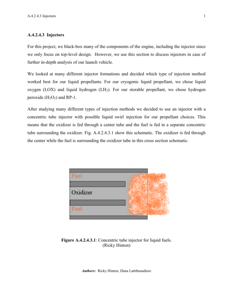
A.4.2.4.3 Injectors 1 A.4.2.4.3 Injectors For this project, we black-box many of the components of the engine, including the injector since we only focus on top-level design. However, we use this section to discuss injectors in case of further in-depth analysis of our launch vehicle. We looked at many different injector formations and decided which type of injection method worked best for our liquid propellants. For our cryogenic liquid propellant, we chose liquid oxygen (LOX) and liquid hydrogen (LH2). For our storable propellant, we chose hydrogen peroxide (H2O2) and RP-1. After studying many different types of injection methods we decided to use an injector with a concentric tube injector with possible liquid swirl injection for our propellant choices. This means that the oxidizer is fed through a center tube and the fuel is fed in a separate concentric tube surrounding the oxidizer. Fig. A.4.2.4.3.1 show this schematic. The oxidizer is fed through the center while the fuel is surrounding the oxidizer tube in this cross section schematic. Figure A.4.2.4.3.1: Concentric tube injector for liquid fuels. (Ricky Hinton) Authors: Ricky Hinton, Dana Lattibeaudiere A.4.2.4.3 Injectors 2 This concentric tube design has good stability characteristics for our cryogenic liquid propellants. For example, the Space Shuttle main engine uses this injection method using LOX and LH2.1 For our storable propellants, we need a slightly better mixing so we can use the same concentric design, but we introduce a swirl to the liquid fuel stream. The liquid fuel swirls around in its concentric tube so when introduced to the oxidizer, a better mixing takes place. In hybrid rocket motors, these injector plates feed oxidizer into the chamber to help atomize the propellant. Typical required pressure drops range from 20% to 30 %.2 In the code, stage, we assume a pressure drop of 20%. The design process of an injector, especially of liquid propellant injectors optimize many of the design parameters and many of the physical processes of the injector that occur simultaneously. For hybrid rocket motors, there exist two basic designs to consider: one that directly injects oxidizer down the port and another design that injects oxidizer into a precombustion chamber where the precombustion chamber gasifies and heats the oxidizer before it flows down the port. In either case, the oxidizer needs to go down the port to react with the propellant. In early works, smaller motors with single ports use injectors that inject oxidizer directly down the port. Larger motors with multiple ports use injectors that inject into a precombustor. Larger motors use individual injectors, but this arrangement has a disadvantage if the ignition requires a hypergolic fuel. If so, then each injector would need its own means of injecting fuel. However, these individual injectors give high combustion efficiencies of 91-93% of equilibrium flow prediction.2 For our choice of oxidizer, H2O2, we consider impinging-like type of injectors. “Like” injectors use two oxidizers or two fuels. If we choose an injector that injects oxidizer into a precombustion chamber, then we must consider the more conventional liquid injectors to provide a uniform spray using injector types such as the showerhead, impinging jets, splash plates and swirl sprays. We also have to consider a length-to diameter (L/D) so the oxidizer has enough time to vaporize. Typical L/D of the precombustor area is about 0.5.2 Authors: Ricky Hinton, Dana Lattibeaudiere A.4.2.4.3 Injectors 3 For our final design, none of our stages uses liquid engines so we did not develop this type of injector design further. This section may provide an insight for future design changes if a liquid engine ever is needed for any of these launch vehicles. As we stated before, we do not have any detailed analysis on hybrid injectors because we only focus on top-level design. References: AAE 439 class notes fall 2007. Professor Hrbud. Injectors: supplementary handout. pg. Ch639a. 2 Humble, R. W., Henry, G. N., Larson, W. J., “Hybrid Rocket Propulsion Systems,” Space Propulsion Analysis and Design, 1st ed., Vol. 1, McGraw-Hill, New York, NY, 1995, pp. 366, 424-425. 1 Authors: Ricky Hinton, Dana Lattibeaudiere
