Analysis of Carbon–iron (Fe–Fe3C) Phase Diagram 1. Experimental
advertisement
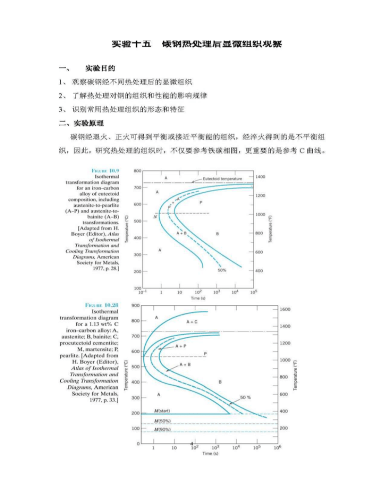
Analysis of Carbon–iron (Fe–Fe3C) Phase Diagram 1. Experimental Objects 1) Observe the microstructures in carbon- iron alloys;2) Analyse the forming process of iron-carbon alloys 2. Introduction 1) About the microscopy magnified and inverted Fig 1 Principle of Optical Microscopy With optical microscopy, the light microscope is used to study the microstructure; optical and illumination systems are its basic elements. For materials that are opaque to visible light, only the surface is subject to observation, and the light microscope must be used in a reflecting mode. Contrasts in the image produced result from differences in reflectivity of the various regions of the microstructure. Investigations of this type are often termed metallographic, since metals were first examined using this technique. Normally, careful and meticulous surface preparations are necessary to reveal the important details of the microstructure. The specimen surface must first be ground and polished to a smooth and mirrorlike finish. This is accomplished by using successively finer abrasive papers and powders. The microstructure is revealed by a surfacetreatment using an appropriate chemical reagent in a procedure termed etching. The chemical reactivity of the grains of some single-phase materials depends on crystallographic orientation. Consequently, in a polycrystalline specimen, etching characteristics vary from grain to grain. Also, small grooves form along grain boundaries as a consequence of etching. Since atoms along grain boundary regions are more chemically active, they dissolve at a greater rate than those within the grains. These grooves become discernible when 1 viewed under a microscope because they reflect light at an angle different from that of the grains themselves.When the microstructure of a two-phase alloy is to be examined, an etchant is often chosen that produces a different texture for each phase so that the different phases may be distinguished from each other. Fig2 Fig 3 (a) Section of a grain boundary (a) Polished and etched grains as they and its surface groove produced by might appear when viewed with an etching; the light reflection optical microscope. (b) Section taken characteristics in the vicinity of from these grains showing how the the groove are also shown. (b) etching characteristics and resulting Photomicrograph of the surface of surface texture vary from grain to grain a polycrystalline specimen of an because of differencescrystallographic in iron-chromium alloy in which the grain orientation boundaries appear dark. 100× 2) Iron-Carbon alloys Iron-carbon alloys are common engineering materials. The microstructure depends on both the carbon content and heat treatment. The equilibrium microstructures of iron-carbon alloys play an important roles on materials’ properties and phase transforming mechanisim. This discussion is confined to very slow cooling of steel alloys, in which equilibrium is continuously maintained. 2 Classification and structure of iron-carbon alloys Carbon steels Classification CARBON WEIGHT(%) Hypoeutectic steels 0.02—0.77 Eutectic steels Hypereutectic steels MICROSTRUCTURE OF EQUILIBRIUM Ferrite+pearlite 0.77 pearlite 0.77—2.11 Pearlite+cementite Iron-carbon alloys only have two phases at room temperature,they are ferrite and cementite. As the carbon content is quite different, the realitive weight percentage of the two basic phases as well as their shape and distribution are different, which make them have different microstructure. Various microscope structrue characters are discussed as follow: a) Ferrite: It is the solid solution which carbon inα-Fe, In the BCC ferrite, only small concentrations of carbon are soluble, the maximum solubility is 0.022 wt% at 727℃and at room temperature, the solubility is only 0.008wt%.Ferrite has low hardness and good ductility, it will show light white in 4% nitric acid alcohol liquor. When the carbon weight increases, the microstructure consists net shape ferrite around the pearlite. b)Cementite: The chemistrical form is Fe3C, which has a high carbon content of about 6.69wt%.It’s a hard and strong phase. The color is light white in 4% nitric acid alcohol liquor.In hyperenutectic steels, it is net shape around pearlite. Both cementite and ferrite are light white in 4% nitric acid alcohol liquor. 3 c) Pearlite It is a mixture of cementite and ferrite.This microstructure is called pearlite because it has the appearance of mother of pearl when viewed under the microscope at low magnifications. The pearlite exists as grains, often termed “colonies”; within each colony the layers are oriented in essentially the same direction, which varies from one colony to another. The thick light layers are the ferrite phase, and the cementite phase appears as thin lamellae most of which appear dark. Many cementite layers are so thin that adjacent phase boundaries are so close together that they are indistinguishable at this magnification, and, therefore, appear dark. In 4% nitric acid alcohol liquor, as different magnifications they have different characters: at about 600X, both thick ferrite and thin cementite are light white colour and the boundary is black; At about 400X, the thin light white colour cementite will be covered by the black boundary and the cementite will be black, at this time, pearlite is the thick light white colour ferrite and black thin cementite; At about 200X, the thick light white colour ferrite can not be observed as well and the pearlite will be dark black colour.As the carbon weight in plain steel is low and the distance between ferrite and cementite is small and even in large magnifications, the pearlite will be dark black colony 3) Mechanical properties of various microstructure Mechanically, pearlite has properties intermediate between the soft, ductile ferrite and the hard, brittle cementite. Table 2 Mechanical properties of ferrite,cementite and pearlite ferrite cementite peartite Hardness(HB) 50—90 750—880 190—230 Tensilestrength(MPa) 190—250 30 Ductility(EL%) 40—50 0 860—900 9—12 4) Calculation the carbon weight in carbon steels We can estimate the carbon weight by microscope. Firstly, estimate the different microstructure’s areas, definely: n:Ferrite area percentage K:Pearlite area percentage B:Cementite area percentage According to Fe―Fe3C phase diagram, at room temperature ferrite has 0.008%wt of carbon, pearlite has 0.77%wt of carbon and cementite has 6.69%wt of carbon, then using level rule, we can know: n × 0.008 To hypo-eutectoid steel : %C= K × 0.77 + 100 100 B ×6.69 K ×0.77 To hyper-eutectoid teel: %C =+ 100 100 4 3. Experimental equipment and materials 1) Carbon steels specimen 2) Microscope 4. The experiment report requested 1) Observe the microstructure characters of samples in turn and draw the microstructures you observed through the microscope. 2) Rank the sequence of four samples from high to low according to the carbon content. 3) Select one specimen and estimate the areas of the different phases.Caculate the carbon content according to the lever-rule. 5 Oberservation the microstucture of carbon steels with heat treatment 1. Experimental Objects 1) Oberserve the microstucture of carbon steels with different heat treatment 2) Understand the heat treatment effect on the microstructures of steels 3) Distinct states and characters with common heat treatment 2. Experimental principles After annealing or normalizing, carbon steels can get equilibrium or close to equilibrium microstructure.But quenching is a nonequilibrium process, we should use not only iron-carbon phase diagram but also C-curve to analyse the microstructure after heat treatment, 6 Carbon steels will show different microstructure as the composition and heat treatments are different. The basic characters of the microstructure will discuss as follow: a) pearlite Pearlite is a mechanical mixture of ferrite and layers cementite.The thickness ratio of the ferrite and cementite layers in pearlite is approximately 8 to 1. However, the absolute layer thickness depends on the temperature at which the isothermal transformation is allowed to occur. At temperatures just below the eutectoid, relatively thick layers of both the -ferrite and Fe3C phases are produced; this microstructure is called coarse pearlite, At these temperatures, diffusion rates are relatively high, such that carbon atoms can diffuse relatively long distances, which results in the formation of thick lamellae.With decreasing temperature, the carbon diffusion rate decreases, and the layers become progressively thinner. The thin-layered structure produced in the vicinity of is termed fine pearlite. b) Bainite The microstructure of bainite consists of ferrite and cementite phases, Bainite forms as needles or plates, depending on the temperature of the transformation; the microstructural details of bainite are so fine that their resolution is possible only using electron microscopy. c)Spheroidite If a steel alloy having either pearlitic or bainitic microstructures is heated to, and left at, a temperature below the eutectoid for a sufficiently long period of time—for example, at about o (700 C ) for between 18 and 24 h—yet another microstructure will form. It is called spheroidite. the Fe3C phase appears as sphere-like particles embedded in a continuous phase matrix. d)Martensite Martensite is a nonequilibrium single-phase structure.Martensite grains take on a lath-like or flake-like appearance.Plain steels (low carbon alloy steels) after quenching will be lath martensite and high carbon steels (high carbon alloy steels) after quenching will be flake martensite.And the middle carbon steels (middle carbon alloy steels) can gain the mixture of two kinds of martensite. 7 e)Retained austenite When the carbon weight is larger than 0.5%, martensite can not transformed completely and in the room temperature there will be retained austenite.Retained austenite is difficult to be corrosive, in the microscope it distribute between martensite grains with light white colour. Retained austensite and martensite can not be distinguished clearly because they are both ligh white colour before tempering, only after tempering, retained austeniste can be distinguished clearly e) Tempered martensite Tempering is accomplished by heating a martensitic steel to a temperature below the eutectoid for a specified time period. Normally, tempering is carried out at temperatures between o o 250 C and 650 C. The microstructure of tempered martensite consists of extremely small and uniformly dispersed cementite particles embedded within a continuous ferrite matrix. Tempered at low temperature, the microstructure is black needle shape. Tempered at middle temperature, ferrite will be almost keep the shape of fomer matensite and cementite will show quite thin grains shape, it’s not easy to be distinguished using the optical microscope. Tempered at high temperature, there are particle cementite grains with equiaxed shape assembled on the ferrite-base. Table 3 different steels samples’microstructure after various heat treatment Heat treatment processing No. Steel 1 2 3 800 4 5 750 6 750 7 8 9 1100 W1-1.0C W1-0.8C microstructure Heat temperature (℃) 1045 W1-1.2C Corrosive solution 750 750 Air cooling Oil quench Water quench Water quench Water quench Water quench Water quench Spherodite annealing 300 oC isothermal Water quench F+P M+F+B M 600 4% nitric acid 200 200 alcohol liquor Tempered M M+F Tempered M+Fe3C Tempered M+Retained A Spherodite Bainite +M+Retained A Cooling methods Tempered temperatur e(℃) 3. Experimental equipments and materials Samples and microscope 4. Experimental report requested 1) Oberserve the microstructure of the specimen and draw the microstructure of the specimen 2) Compare the microstructure and properties difference between martensite and tempered martensite. 8

