Free Body Diagram
advertisement
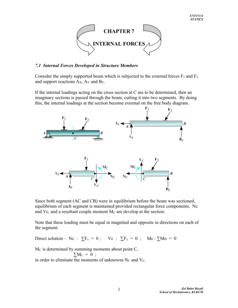
ENT151/4 STATICS CHAPTER 7 INTERNAL FORCES 7.1 Internal Forces Developed in Structure Members Consider the simply supported beam which is subjected to the external forces F1 and F2 and support reactions AX, AY and BY. If the internal loadings acting on the cross section at C are to be determined, then an imaginary sections is passed through the beam, cutting it into two segments. By doing this, the internal loadings at the section become external on the free body diagram. Since both segment (AC and CB) were in equilibrium before the beam was sectioned, equilibrium of each segment is maintained provided rectangular force components, Nc and Vc, and a resultant couple moment MC are develop at the section. Note that these loading must be equal in magnitud and opposite in directions on each of the segment. Direct solution – Nc : ∑Fx = 0 ; Vc : ∑Fy = 0 ; Mc : ∑Mo = 0 MC is determined by summing moments about point C, ∑MC = 0 ; in order to eliminate the moments of unknowns NC and VC. 1 Zol Bahri Razali School of Mechatronics, KUKUM ENT151/4 STATICS - where V = shear force N = Normal force M = Bending Moment My = torsional / twisting moment All resultant force /moment acts on the center of centroid (c) of the section cross area. Free Body Diagram Frame and machine - multi force members -subjected to internal normal, shear and bending loadings. Instead, we must dismember the frame and determine the reaction. Note : We cannot apply the three equation of equilibrium to obtain these nine unknown. 2 Zol Bahri Razali School of Mechatronics, KUKUM ENT151/4 STATICS Analysis Before the member is ‘cut’, determined the all members support reaction. Keep all the forces, moments at exact locations. Draw FBD of the segment that has the least number of loads on it (x,y,z components) Coplaner system only N, V & M Moments should summed at section passing through centre EXAMPLES Example 7-1 (pp 327) Example 7-2 (pp 328) Example 7-3 (pp 329) Example 7-4 (pp 330) Example 7-5 (pp 331) Example 7-6 (pp 332) 3 Zol Bahri Razali School of Mechatronics, KUKUM ENT151/4 STATICS 7.2 Shear and moment equations and diagram Beams are structural members which are design to support loadings applied perpendicular to their axes. In general, beams are long, straight bars, constant crosssectional areas. Often they are classified as to how they are supported. Simply supported beam – is pinned at one end and roller support at the other. Centilever beam – is fixed at one end and free at the other. The actual design of a beam - the variation of the V - internal shear force / shear diagram M - bending moment / bending moment diagram, acting at each point along the axis of the beam. The variation of V and M as functions of the position x along the beam’s axis can be obtain by using the method of sections. It is necessary to section the beam at an arbitrary distance x from one end rather then at a specified point. If the result are plotted, the graphical variation of V and M as functions of x are termed the shear diagram and bending moment diagram. Because of the internal shear and bending moment functions will be discontinous, the functions must be determined for each segment of the beam located between any two discontinuities of loading. 4 Zol Bahri Razali School of Mechatronics, KUKUM ENT151/4 STATICS Procedure for analysis Determined all the reactive forces and couple moment acting on the beam, and resolve all the forces into components acting perpendicular and parallel to the beam axis. Specify separate coordinates and having an origin at the beam’s left-end Section the beam perpendicular to the axis. Shear V-summing forces perpendicular to the axis Moment M-slimming moments about section end. Plot the shear diagram (V vs x) and moment diagram (M vs x) EXAMPLES Example 7-7 (pp 342) Example 7-8 (pp 343) 7.3 Relations Betwen Distributed Load, Shear and Moment Shear and moment function Specify separates cordinates x having an origin at the beam’s left end and extending to region of the beam between the concentrated force and/or couple moment, or where there is no discontinuity of distributed loading. Section the beam if its axis at each distance x and draw the free body diagram of one of the segments. Be sure V and M are shown acting in their positive sense. The shear V obtained by summing forces perpendicular to the beam’s axis. The moment M is obtained by summing moments about the sectioned end of the segment. Example : ∑Fy = 0 ; V = 2.5 kN ∑M = 0 ; M = 2.5 x kN.m 5 Zol Bahri Razali School of Mechatronics, KUKUM ENT151/4 STATICS A free body diagram for the left segment of the shaft extending a distance x within the region BC ∑Fy = 0 ; ∑M = 0 ; V = 2.5 kN M = (10 - 2.5 x )kN.m Shear and bending moment diagram Plot the shear diagram ( V versus x) and the moment diagram ( M versus x). If compute values of the function describing V and M are positive, the values are plotted above the x axis, whereas the negative values are plotted below the x axis. Generally, it is convenient to plot the shear and bending-moment diagrams directly below the free body diagram of the beam. Example: The shear diagram indicates that the internal shear force always 2.5 kN (positive) within shaft segment AB. Just to the right of point B, the shear force changes sign and remains at the constant value of -2.5 kN for segment BC. 6 Zol Bahri Razali School of Mechatronics, KUKUM ENT151/4 STATICS The moment diagram start at zero, increase linearly to point B at x = 2 m, where Mmax = 2.2 kN (2 m ) = 5kN.m, then thereafter decrease back to zero. EXAMPLES Example 7- 9 (pp 351) Example 7-10 (pp 352) Example 7-11 (pp 353) Example 7-12 (pp 354) EXERCISES Exercise 7 - 2 Exercise 7 - 4 Exercise 7 - 10 Exercise 7 - 33 Exercise 7 - 49 Exercise 7 - 59 Exercise 7 - 86 7 Zol Bahri Razali School of Mechatronics, KUKUM


