factsheet for partnership field validation test
advertisement
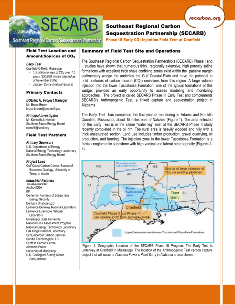
secarbon.org Southeast Regional Carbon Sequestration Partnership (SECARB) Phase III Early CO2 Injection Field Test at Cranfield Field Test Location and Amount/Sources of CO2 Early Test Cranfield Oilfield, Mississippi - 1.5 million tonnes of CO2 over 1.5 years (250,830 tonnes injected as of November 2009) - Jackson Dome (Natural Source) Primary Contacts DOE/NETL Project Manager Mr. Bruce Brown bruce.brown@doe.netl.gov Principal Investigator Mr. Kenneth J. Nemeth Southern States Energy Board nemeth@sseb.org Field Test Partners Primary Sponsors U.S. Department of Energy National Energy Technology Laboratory Southern States Energy Board Summary of Field Test Site and Operations The Southeast Regional Carbon Sequestration Partnership’s (SECARB) Phase I and II studies have shown that numerous thick, regionally extensive, high porosity saline formations with excellent thick shale confining zones exist within the passive margin sedimentary wedge the underlies the Gulf Coastal Plain and have the potential to hold centuries of carbon dioxide (CO2) emissions from this region. A large volume injection into the lower Tuscaloosa Formation, one of the typical formations of this wedge, provides an early opportunity to assess modeling and monitoring approaches. The project is called SECARB Phase III Early Test and complements SECARB’s Anthropogenic Test, a linked capture and sequestration project in Alabama. The Early Test has completed the first year of monitoring in Adams and Franklin Counties, Mississippi, about 15 miles east of Natchez (Figure 1). The area selected for the Early Test is in the saline “water leg” east of the SECARB Phase II study recently completed in the oil rim. The rural area is heavily wooded and hilly with a thick unsaturated section. Land use includes timber production, gravel quarrying, oil production, and farming. The injection zone in the lower Tuscaloosa Formation is a fluvial conglomeritic sandstone with high vertical and lateral heterogeneity (Figures 23). Project Lead Gulf Coast Carbon Center, Bureau of Economic Geology, University of Texas at Austin Industrial Partners ( in alphabetical order) Anchor/QEA BP Center for Frontiers of Subsurface Energy Security Denbury Onshore LLC Lawrence Berkeley National Laboratory Lawrence Livermore National Laboratory Mississippi State University National Risk Assessment Program National Energy Technology Laboratory Oak Ridge National Laboratory Schlumberger Carbon Services Sandia Technologies LLC Scottish Carbon Centre Alabama Power University of Mississippi U.S. Geological Survey Menlo Park/Jackson Figure 1. Geographic Location of the SECARB Phase III Program. The Early Test is underway at Cranfield in Mississippi. The location of the Anthropogenic Test carbon capture project that will occur at Alabama Power’s Plant Barry in Alabama is also shown. The Bureau of Economic Geology (BEG) has partnered with Denbury Onshore LLC to monitor 30 months the injection at a rate of one million tonnes of CO2 per year to guide evolution from experimental to commercial monitoring protocols as well as rationale develop an improved basis for estimation of sequestration capacity. Four integrated programs are in operation. The high volume injection Test (HiVIT) program started April 1, 2009 at an initial rate of 40,000 tonnes of CO2 per month, with monitoring via pressure and fluid sampling though far-field wells, and regional groundwater monitoring conducted by the University of Mississippi and Mississippi State. The HiVIT reached the one million tonne/year target rate in December, 2009 and the 1.5 Million tonne stored target in spring, 2011. The detailed area study (DAS) is designed to allow observation of fluid flow through the rock volume between two 10,700 ft deep instrumented wells through an innovative cross-well multiphysics monitoring program (Figure 4). The well-based program engineered by Sandia Technologies LLC includes time-lapse seismic tomography, combined with LBNL continuous active seismic source monitoring (CASSM), LLNL cross-well electrical resistance tomography, abovezone pressure monitoring provided by Promore, fiber-optic distributed temperature, time-laps wireline monitoring by Schlumberger, high-frequency sampling of fluids for natural and introduced tracers using the U-tube. The geomechanical test (Pinnacle, Weston, LBNL) attempted microseismic monitoring between two closely spaced wells on either side of the non-transmissive eastern limb of the crestal graben. The “P area” is testing surface monitoring strategies in an area where complex soil gas environments including well pads, pits from historic oil field operations and plants complicate interpretation of leakage signal. Methane is anomalously high, however no CO2 leakage has been detected. Anchor –QEA provides modeling support. 2 Figure 3. Characterization of the Tuscaloosa Formation injection zone for the early test has been nearly completed. Southeast Regional Carbon Sequestration Partnership Phase III Early CO2 Injection Field Test Figure 4. An injection well and two closely spaced observation wells at the Detailed Area Study (DAS) allow quantitative assessment of flow using multiple types of cross-well monitoring. Figure 5. Study at the “P area” is developing an improved understanding of soil gas monitoring methods in an area with typical infrastructural complexities and a methane anomaly.. Characterization is recognized as the cornerstone of monitoring and modeling, and the team has invested heavily in wireline logs, core analysis of key reservoir and confining intervals, fluid sampling, hydrologic testing, and extensive and diverse laboratory follow-up. A quantitative static geocellular model has been constructed in Petrel and input into GEMCO2 for assessment of multiphase flow in the Phase II and the HiVIT. A year of design discussions guided selection of the monitoring program. The monitoring approach focused on the advancing research-oriented objectives (listed above) and balanced the opportunities and uncertainties presented by this site with cost, value, and risk of research success. The team recognized that this is one of a series of tests conducted internationally and in the US, which allowed us to focus heavily on method development and scientific objectives, because of the relatively high security offered by this site and operator. The project team selected three focus areas: the DAS to examine multiphase fluid flow and pressure at the interwell scale: the P site to experiment with effective near surface monitoring strategies at a P&A well site, and the GMT to look at sub-fracture stress near a non-trans missive fault. Injection rate was measured as primary signal. At the DAS, two observation wells, arrayed as a transect toward the down-dip plume edge, sampled a segment through the evolving pressure field and plume. Injection rates were stepped during the 18 month monitoring period to provide an opportunity to measure pressure response, this was linked to other metrics especially introduced tracers. Time-lapse difference from baseline was used as a primary tool. Bottom-hole pressure on wireline is the major signal. Redundancy proved valuable, as tool durability was variable. Real-time output for the array controlled the timing of monitoring. U-tube sampling was used for high frequency tracer chromatography (PFT, SF6, noble gasses and natural tracers). Cross-well tools include repeat cross-well tomography, continuous active source seismic monitoring (CASSM) and real-time cross-well electrical resistance tomography (ERT). Walk away and 3-D VSP was conducted in time lapse coordinated with repeat 3-D survey over the HiVIT. Fiber-optic distributed temperature was installed on the casing in one observation well and the tubing of the other. A surface monitoring experiment is using nested soil gas and groundwater sample wells to test natural flux from one near-surface CO2 reservoir (aquifer-vadose-zone-soil-atmosphere) to another. This will determine natural variability and assess the leakage signal that could be detected above background variability at a site with the types of complexities that are expected at a commercial site. A suite of subsurface modeling tools are in use, including analytical assessment of pressure from gas storage literature, one-dimensional (1-D) seal flux assessment, MODFLOW for the pressure modeling in the single phase region, and GEMCO2 for the two phase fields are in use. For geochemical assessments PHREEQC and Geochemists workbench are the major modeling tools in use for single phase regions; CORE2D and TOUGHREACT are used to multiphase reactive volume transport and multiphase flow. 3 Southeast Regional Carbon Sequestration Partnership Phase III Early CO2 Injection Field Test Table 1 Measurement Technologies Employed at Phase III Early Test site Measurement Technique Measurement Parameters Application Introduced – noble Dissolution of CO2 into brine Significant uncertainties in mass balance and pressure response gasses/partitioning tracers is the amount of CO2 dissolved. The U-tube sampler was used to (DAS) obtain high quality- high frequency fluids with intact tracers to assess dissolution and flow processes Produced fluid composition (DAS, HiVIT) Gasses and tracers via mass spectrometer, Selected major and minor cations, organics via GC, stable isotopes, noble gases. Pressure transducers on wireline with real-time readout Validation of well log and cross-well CO2 detection, index of rockwater reaction. Distributed down hole temperature with heater cable (DAS) Pulsed neutron reservoirs saturation; cased hole sonic Measure zones of behindcasing fluid replacement and fluid movement CO2 saturation Additional data to constrain flow units, especially to determine flow-unit thicknesses under relevant conditions. Also assessment of cement integrity. Distribution of CO2 at measurements points, model match, validation and quantification of CASSM and cross-well ERT. Time-lapse 3-D seismic imaging (surface deployed) Change from baseline Extent of CO2 plume, lateral coalescence of plume from multiple injectors. Time-lapse VSP (walk away and 3-D) Increased vertical resolution Complements and refines 3-D interpretation near DAS, refine down-dip plume edge measurement. Continuous Active Source Seismic Monitoring (CASSM); Cross-well seismic tomography Passive seismic monitoring Detect timing of CO2 movement cross the plane of measurement Co-inversion with ERT Assess value of technique in setting well below fracture pressure Technique assessment Above-zone pressure monitoring Assess leakage signal (possible through well completions because of poor cement bond) Continuation from Phase II to obtain long record ; behind casing pressure at DAS Cross-well electrical resistance tomography (ERT) Soil gas Improve measurement of saturation Tool development will extend the range of cross-well measurement of saturation and improve the rigor of history match and seismic inversion. Determine sensitivity of soil gas techniques under regional conditions. Follow-on-tracer test. Bottom-hole pressure injection (DAS) Aquifer monitoring 4 Measure N2/ O2/CO2 /CH4 ratios, introduced tracers, stable isotopes and noble gasses in vadose zone at plugged and abandoned well site Quarterly fresh water sampling at 200 ft depth at injection well sites, selected cations and anions, noble gasses. Southeast Regional Carbon Sequestration Partnership Phase III Early CO2 Injection Field Test Assess relationship between pressure field and multiphase field. Assessment of method in compact possibly contaminated setting, directly regulated recourse. follow-on tracer test. Project Cost and Key Dates PHASE III PROJECT COST Dollars Percent KEY PROJECT DATES EARLY TEST DOE Share $76,981,260 69.10% Baseline Completed Non-DOE Share $34,432,171 30.90% Drilling Operations Begin Total Value $111,413,431 (includes $2,444,000 for Federal Laboratories) Injection Operations Begin MVA Events *Includes all Tasks for the Phase III Program Injection Operations End 9/2008 - 11/2010 (phased in five test areas) 4/2008 first new drill well 8/2009 DAS wells drilled (phased, 14 injection wells) 10/2008 in area 12/2009 DAS injection 4/2009 - 12/2010 2/2011 propose reduce DOE spend on CO2 This material is based upon work supported by the U.S. Department of Energy National Energy Technology Laboratory under DE-FC26-04NT42590. 5 Southeast Regional Carbon Sequestration Partnership Phase III Early CO2 Injection Field Test
