fuelcell - Clarkson University
advertisement

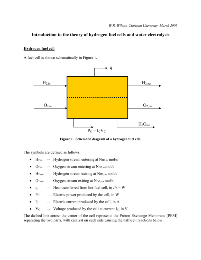
W.R. Wilcox, Clarkson University, March 2005 Introduction to the theory of hydrogen fuel cells and water electrolysis Hydrogen fuel cell A fuel cell is shown schematically in Figure 1. q H2,in H2,out O2,in O2,out H2Oout PC = ICVC Figure 1. Schematic diagram of a hydrogen fuel cell. The symbols are defined as follows: H2,in -- Hydrogen stream entering at NH2,in mol/s O2,in -- Oxygen stream entering at NO2,in mol/s H2,out -- Hydrogen stream exiting at NH2,out mol/s O2,out -- Oxygen stream exiting at NO2,out mol/s q -- Heat transferred from hot fuel cell, in J/s = W PC -- Electric power produced by the cell, in W IC -- Electric current produced by the cell, in A VC -- Voltage produced by the cell at current IC, in V The dashed line across the center of the cell represents the Proton Exchange Membrane (PEM) separating the two parts, with catalyst on each side causing the half-cell reactions below: Oxidation: Reduction: H2 = 2H+ + 2e½ O2 + 2H+ + 2e- = H2O (1) (2) The hydrogen ions (protons) liberated on the oxidation side must diffuse across the membrane in order to react with the oxygen on the other side, thereby producing water. The electrons liberated on the oxidation side flow around an external circuit in order enter on the reduction side.1 If we add these two reactions together we get the overall reaction for the cell: Overall: H2 + ½ O2 = H2O (3) The power produced by the cell comes from the Gibbs free energy of this reaction, Gr , which depends on the pressure of the components and the temperature of the cell. In reality, neither the hydrogen nor the oxygen is pure (i.e., yH2 1 and yO2 1). For example, if the hydrogen and oxygen are produced by electrolysis of water, there would be some water vapor present in both. Air is used as a source of oxygen in most applications, and air is only about 21mol% oxygen (yO2 0.21). If we assume that the water is pure and that the oxygen and hydrogen streams are ideal gas mixtures, then we may write the following expression for the free energy of the overall reaction: G r G 0f (T, H 2O) RT ln( y H2 y1O/22 P3 / 2 ) (4) where G 0f (T, H 2O) 2 is the standard free energy of formation in J/mol of water from its components at 1 bar pressure and temperature T (in K), R is the gas constant (8.314 J/mol/K = 8.314 m3 Pa/mol/K, yH2 is the mole fraction of H2 on the H2 side of the cell, yO2 is the mole fraction of O2 in the gas on the O2 side of the cell, and P is the total pressure in the cell in bar. Note that Gr is negative for fuel cells, i.e. the product (water) has a lower free energy than the reactants (hydrogen and water). This loss of chemical energy is converted to electrical energy in the cell. If there are no losses in the system, the chemical energy decrease and the electrical energy gain are equal and the equilibrium cell potential EC is given by: EC G r n (5) 1 By convention, electric current is flow of positive charges, so the electric current is in the direction opposite that of the electrons, i.e. from the oxygen side to the hydrogen side. Values of G 0f for this reaction are tabulated versus temperature on pages 1273 and 1274 of the JANAF Thermochemical Tables, Third Edition, Part II, in the Journal of Chemical Reference Data, volume 14 (1985) Supplement No. 1 (Clarkson Library call number 530.021). The value is larger (more negative) for liquid water as the product than for water vapor as the product. 2 where n is the number of equivalents of electrons transferred between the half cells for each mole of reaction as written (here, n = 2), and F = 96,500 C/equivalent of electrons and is known as the Faraday constant.3 At 25oC, with liquid water as the product, the value of G 0f is -237 kJ/mol, which gives 1.23 V for E 0C . This is the maximum voltage the cell can produce for pure hydrogen and oxygen feeds at 1 bar pressure, and would be expected only when no external current is drawn (open circuit, i.e., IC = 0). That is, E 0C lim VC IC 0 (6) The current produced by the fuel cell is directly related to the amount of reaction that occurs, because each mole of hydrogen consumed produces 2 equivalents of electrons (i.e., n = 2). If the hydrogen feed is pure (yH2 = 1) and there is no hydrogen exhausted from the cell, then at steady state4 the cell current IC is: IC = NH2 nF where NH2 is the rate of feed to the fuel cell in mol/s.5 PC = ICVC (7) The power produced in the fuel cell is: (8) The maximum power possible is: Pmax = ICEC = NH2nF(-Gr/nF) = - NH2Gr (9) The cell efficiency is defined as: PC/Pmax = VC/EC = - nFVC/Gr (10) Why is the efficiency less than 1? Because there are many losses in a fuel cell producing a finite amount of current, particularly: The drop in H2 and O2 concentrations as they diffuse to the catalyst particles where the halfcell reactions occur. The drop in H+ concentration as it migrates across the membrane separating the hydrogen side from the oxygen side of the cell. The Faraday constant F is the product of Avogadro's number, NA = 6.02x10²³electron/equivalent, and the elementary charge on an electron, e = 1.6x10⁻¹⁹C/electron (where C is the coulomb, i.e. 1 ampere.s). 3 4 "Steady state" means that nothing is changing with time, e.g. the hydrogen flow rate and current are constant. This is NOT the same as "equilibrium," which here means zero current and zero reaction. (Interestingly, in some languages they use the same word for "steady state" and for "equilibrium," which causes even more confusion than for English-speakers.) 5 If the hydrogen feed rate is measured volumetrically, e.g. cc/min, this must be converted to mol/s using the ideal gas law. The finite reaction rates of the two half-cell reactions, particularly the oxygen reaction. Resistance to the flow of electrons is generally negligible compared to these chemical resistances. We can, however, think of the sum of all the losses as equivalent to an internal electrical resistance or impedance, and draw the equivalent circuit shown in Figure 2. Rint VC EC Rext IC Figure 2. Equivalent circuit showing an internal impedance to current flow. Here, the fuel cell is modeled as a battery producing constant voltage EC combined with an internal impedance Rint, yielding cell voltage VC that is available to provide current IC to the external load Rext. From ohm's law: IC = VC/RC = EC/(Rint+ Rext) (11) Solving this we find: Rint = (EC -VC)/IC (12) which enables us to calculate Rint versus IC from measurements of VC) and IC.6 Water electrolysis cell From a chemical viewpoint, water electrolysis is just the reverse of the hydrogen fuel cell. In this case the applied voltage PC must be greater than the equilibrium voltage EC in order to drive the reactions in the reverse direction. The efficiency is now given by -Gr/nFVC and the internal impedance Rint by (VC - EC)/IC. 6 Since most of the losses in the cell vary non-linearly with the current, we expect the internal impedance to vary with current. Some good web sites • • • • • • PEM fuel cell schematic diagram The father of the fuel cell The first practical fuel cell http://www.fuelcells.org/ The father of modern thermodynamics J. Willard Gibbs: scientist & mathematician


