Oberst Apparatus
advertisement
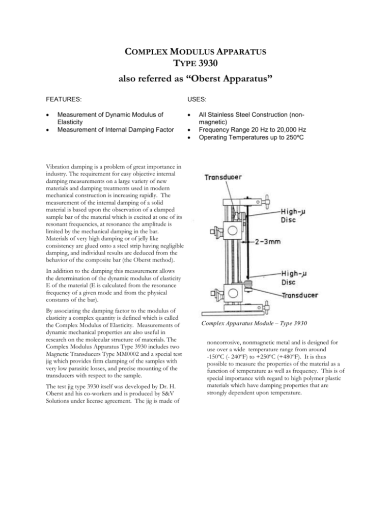
COMPLEX MODULUS APPARATUS TYPE 3930 also referred as “Oberst Apparatus” FEATURES: USES: Measurement of Dynamic Modulus of Elasticity Measurement of Internal Damping Factor All Stainless Steel Construction (nonmagnetic) Frequency Range 20 Hz to 20,000 Hz Operating Temperatures up to 250ºC Vibration damping is a problem of great importance in industry. The requirement for easy objective internal damping measurements on a large variety of new materials and damping treatments used in modern mechanical construction is increasing rapidly. The measurement of the internal damping of a solid material is based upon the observation of a clamped sample bar of the material which is excited at one of its resonant frequencies, at resonance the amplitude is limited by the mechanical damping in the bar. Materials of very high damping or of jelly like consistency are glued onto a steel strip having negligible damping, and individual results are deduced from the behavior of the composite bar (the Oberst method). In addition to the damping this measurement allows the determination of the dynamic modulus of elasticity E of the material (E is calculated from the resonance frequency of a given mode and from the physical constants of the bar). By associating the damping factor to the modulus of elasticity a complex quantity is defined which is called the Complex Modulus of Elasticity. Measurements of dynamic mechanical properties are also useful in research on the molecular structure of materials. The Complex Modulus Apparatus Type 3930 includes two Magnetic Transducers Type MM0002 and a special test jig which provides firm clamping of the samples with very low parasitic losses, and precise mounting of the transducers with respect to the sample. The test jig type 3930 itself was developed by Dr. H. Oberst and his co-workers and is produced by S&V Solutions under license agreement. The jig is made of Complex Apparatus Module – Type 3930 noncorrosive, nonmagnetic metal and is designed for use over a wide temperature range from around -150ºC (- 240ºF) to +250ºC (+480ºF). It is thus possible to measure the properties of the material as a function of temperature as well as frequency. This is of special importance with regard to high polymer plastic materials which have damping properties that are strongly dependent upon temperature. Description The figure shows a sketch detailing the mechanical construction of the test jig. The guide pillar has two adjustable supports for the transducers. The main clamping arrangement for the sample bars is located at the top of the apparatus. This clamping arrangement is used separately when measurements are made on samples clamped at one end only (the common type of operation). When measurements are to be made on samples clamped at both ends, a second clamping arrangement is attached to the guide underneath the lower transducer support. The transducers can be moved freely along the guide pillar and can be positioned so that their axes of symmetry are either at 90 degrees or parallel to the longitudinal axis of the sample bar. In this way the samples can be excited either from the side or from underneath. Specifications Sample Bar Dimensions: Free length: From 75 to 220 mm (3" to 8 ½"). Section: Max. 12 x 12 mm (½ x ½"). Dimensions and Weight of Type 3930: Total height: 33 cm (13"). Weight: 6.8 kg (15 lbs.). Accessories Included: 2 Magnetic Transducers Type MM 0002 with cables and high- discs. Main Characteristics of the Transducer Type MM 0002 The Magnetic Transducer Type MM 0002 is a variable reluctance (moving-iron) device which can be used as a velocity sensitive vibration pick-up or an electromagnetic vibration exciter. If the sample is made of a nonmagnetic material a high permeability iron disc must be glued onto the sample to complete the magnetic circuit. Sensitivity: 1.5 mV/cm/sec. when the mean distance between the housing of the electromagnet and the high- disc is 2 mm. The sensitivity in front of a large iron plate is about 2.5 times (8 dB) higher. Frequency Response: The velocity sensitivity is essentially independent of the frequency (varies less than ± 10 % up to 2,000 Hz). System Requirements dual channel FFT or digital filter spectrum analyzer (B&K 3560 recommended) random noise generator (i.e. B&K 3107 module) power amplifier (i.e. B&K 2706) Recommended Accessories Modal Analysis Software with curve fitting/parameter extraction capability S&V Solutions signal amplifier Internal Impedance: 1800 in series with 400 mH (the resistance may be higher, especially at high frequencies when working in front of massive iron parts). Maximum Input Voltage. 100 Volts at normal ambient temperature, and 20 Volts at maximum ambient temperature 250ºC (480ºF) corresponding to maximum continuous current of 50 mA and 10 mA respectively. Distortion: The moving-iron transducer is basically a non-linear device because of the square-law relationship between force and distance. However, the distortion will not exceed 5 % if the relative peak-to-peak amplitude d/d0 is smaller than 5 %. Environment: Temperature variations (from very low temperature up to + 250ºC/480ºF), ambient pressure and humidity have practically no influence on the open circuit sensitivity of the transducer. Weight (excluding cable): 52 g. Accessories Included: High temperature cable and 10 high- discs.

![[17] P.Stiuca, V.Chiroiu, CMNicolescu, ch.12, On the mechanical](http://s3.studylib.net/store/data/007616744_2-1887c0729fbaf3ba82043651e9efafea-300x300.png)