MEEN 689-602 Back-to-Basic Optics and Optical Techniques
advertisement
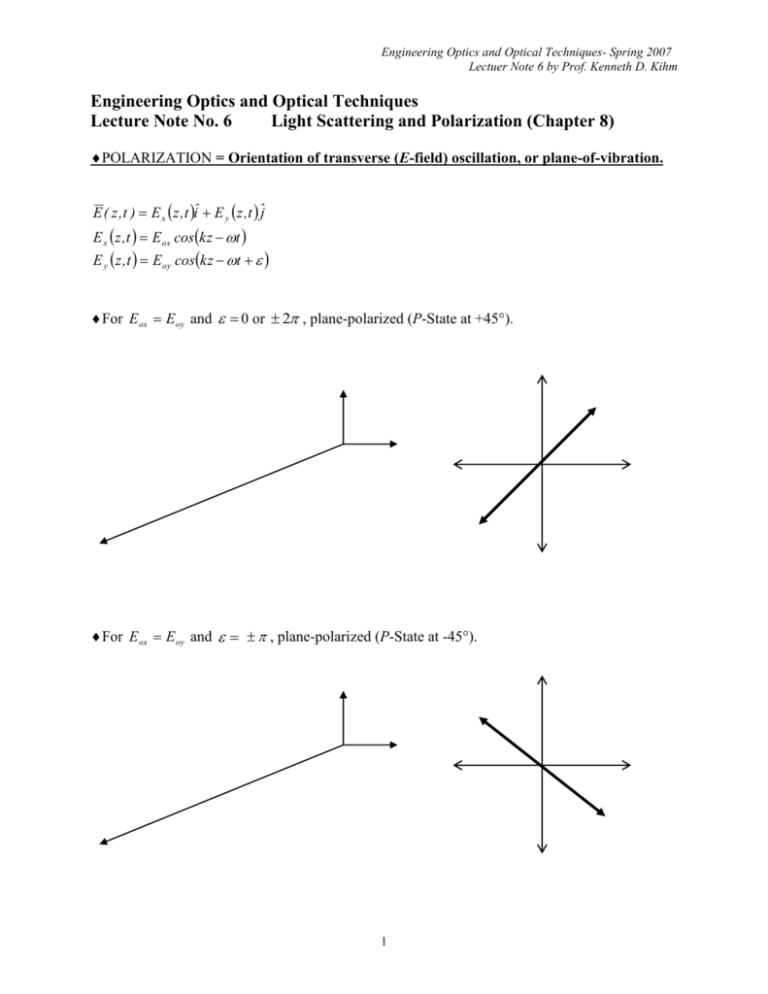
Engineering Optics and Optical Techniques- Spring 2007 Lectuer Note 6 by Prof. Kenneth D. Kihm Engineering Optics and Optical Techniques Lecture Note No. 6 Light Scattering and Polarization (Chapter 8) POLARIZATION = Orientation of transverse (E-field) oscillation, or plane-of-vibration. E ( z ,t ) E x z ,t î E y z ,t ˆj E x z ,t E ox coskz t E y z ,t E oy cos kz t For E ox E oy and 0 or 2 , plane-polarized (P-State at +45). For E ox E oy and , plane-polarized (P-State at -45). 1 Engineering Optics and Optical Techniques- Spring 2007 Lectuer Note 6 by Prof. Kenneth D. Kihm For E ox E oy and / 2, right-circular polarized (R-State). … Looking down the z-axis toward the origin, we see the E-field vector rotates clockwise as the wave advances toward the observer. For E ox E oy and / 2, left-circular polarized (L-State). For Eox Eoy , elliptically polarized (E-State) *Natural Light: randomly polarized or unpolarized. *Laser: highly (usually linearly) polarized. 2 Engineering Optics and Optical Techniques- Spring 2007 Lectuer Note 6 by Prof. Kenneth D. Kihm POLARIZERS (Figs. 8.10 and 8.11) Wire-grid polarizer: The y-component of the E-field drives the free electrons along the wire, which collide with atoms, heating the wire to be thermally diffused. The wire separation must be in the order of … impractical to manufacture and handle for visible spectrum, but useful for IR or microwave ranges. (Fig. 8.12) Malus Law: I I 0 cos 2 E E 0 cos Dichroic crystals: Specific atomic configuration of a crystal allows an optic axis, along which the parallel E-field passes, but the perpendicular E-field is absorbed. (ex. Tourmaline crystals, Fig. 8.13) Polaroid sheet: Molecular analog of the wire grid. Most commonly used one. 3 Engineering Optics and Optical Techniques- Spring 2007 Lectuer Note 6 by Prof. Kenneth D. Kihm BIREFRINGENCE: Optically Anisotropic material, i.e., directional variation of n Model of optically anisotropic atom (Figs. 8.14 and 8.15) o k me For the present model, k x k y k z and ox oy oz . For a given o , n x n n y n z n . Fig. 8.15 Thus, V (propagation speed of E-vector field parallel to the optic axis-x) > V (propagation speed of E-field perpendicular to the optic axis-y or z). Ordinary wave “o”: no c V [E-vector perpendicular to the OA] Extraordinary wave “e”: ne c V [E-vector parallel to the OA] Measure of birefringence: ne no … either “+” or “-“ (Table 8.1 on p. 343) 4 Engineering Optics and Optical Techniques- Spring 2007 Lectuer Note 6 by Prof. Kenneth D. Kihm Birefringence Crystal (e.g. calcite) E-vector Optic axis: “o” wave [No change since no E-vector compt. is parallel to OA] [No anisotropic effect] E-vector has a parallel component to Optic axis: “e” wave … results in separation of polarities 5 Engineering Optics and Optical Techniques- Spring 2007 Lectuer Note 6 by Prof. Kenneth D. Kihm Optical (Phase) Retarders … -plate [rotates P-State by 90] 2 -plate [convert P-State to R- or L-State] 4 Calcite crystal of thickness d with V V and ne ( 1.4864) no (1.6584) d Optic Axis 2 Phase differential between o- and e-waves: The Half-Wave plate (Fig. 8.38): 2m 1 The Quarter-Wave plate (Fig. 8.40): 4m 1 6 2 OPD o 2 o d no ne and d and d 2m 1o 2 no ne 4m 1o 4 no ne Engineering Optics and Optical Techniques- Spring 2007 Lectuer Note 6 by Prof. Kenneth D. Kihm Optical Compensator – a Controllable Retarders: This device impresses variable phase differential 1 2 o d 1 no ne and 2 Overall phase differential is: 1 2 2 o d1 d 2 no ne 7 2 o d 2 no ne Engineering Optics and Optical Techniques- Spring 2007 Lectuer Note 6 by Prof. Kenneth D. Kihm POLARIZATION BY REFLECTION e-dipole does not radiate in the direction parallel to its oscillation direction. If the dipole oscillation of the refracted ray is directed parallel to the reflected ray, the reflected ray does not carry the polarity component in its own ray direction, i.e., Snell’s law: ni sin i nt sin t t 90 p p tan 1 nt … Brewster’s angle ni The same conclusion is made by considering the Amplitude Reflection Coefficient for the Efield parallel to the plane of incidence, Eq. (4.43) and Fig. (4.41), r tan i t 0 tan i t Since i t , i t or 2 8 i p tan 1 nt ni Engineering Optics and Optical Techniques- Spring 2007 Lectuer Note 6 by Prof. Kenneth D. Kihm STOKES VECTOR DESCRIPTION OF BEAM POLARIZATION Natural or randomly polarized light can be decomposed into two primary components, i.e., E E x E y Eox coskz t x iˆ Eoy cos kz t y ˆj Definition of Stokes Parameter S 0 E ox 2 E oy 2 S1 Eox 2 Eoy 2 S 2 2 E ox E oy cos where y x . S 3 2 E ox E oy sin Normalized by S 0 , then, for example, for an unpolarized beam; S0 1 S1 Eox Eox S2 S0 1 S1 0 S1 1 2 S2 0 S2 0 2 S3 0 S3 0 Eoy 2 2 Eoy 2 2 Eox Eoy cos Eox S3 S0 1 2 2 Eoy 2 E ox E oy sin E ox 2 E oy vertical P-state ( Eox 0 ); Degree of Polarization S V 2 1 S 22 S 32 S0 1/ 2 = 1 for completely polarized (all in Table 8.5) = 0 for randomly polarized. 9 Engineering Optics and Optical Techniques- Spring 2007 Lectuer Note 6 by Prof. Kenneth D. Kihm S 0 S Stokes vector 1 , carries complete information on E-field components and polarization. The S 2 S3 vector is superposable since it represents scalar intensity magnitudes. See Table 8.5 for the list of Stokes vectors. MUELLER MATRIX DESCRIPTION OF POLARIZERS Table 8.6 for list of Mueller matrices. Horizontal linear polarizer passes only horizontal P-state E-field. 1 1 1 2 0 0 1 0 0 1 1 1 0 0 1 1 0 0 0 0 0 0 0 0 0 0 1 1 1 2 0 0 1 0 0 1 0 1 0 0 1 0 0 0 0 0 0 0 0 0 0 0 Linearly polarized E-field that is either parallel or perpendicular to the fast axis of a quarter wave plate remains unchanged. 1 0 0 0 0 1 1 0 1 1 0 0 1 0 0 0 1 0 0 0 0 1 0 0 1 0 0 0 0 1 1 0 1 1 0 0 1 0 0 0 1 0 0 0 0 1 0 0 Incident E-field at 45 w.r.t. the fast axis of a quarter wave plate comes out as a circular polarized E-field. 1 0 0 0 0 1 1 0 0 0 … L-state 0 0 1 1 0 0 1 0 0 1 0 1 0 0 10 Engineering Optics and Optical Techniques- Spring 2007 Lectuer Note 6 by Prof. Kenneth D. Kihm Example Imagine that we pass a unit-irradiance unpolarized wave through a linear horizontal polarizer. Determine the Stokes vector of the emerging wave. S 0 1 1 S 1 1 1 1 S 2 2 0 0 0 0 S 3 0 0 1 1 / 2 1 0 0 0 1 / 2 1 1 … Horizontal P-state with ½ irradiance 0 0 0 0 2 0 0 0 0 0 0 11 Engineering Optics and Optical Techniques- Spring 2007 Lectuer Note 6 by Prof. Kenneth D. Kihm JOHNS VECTORS (Beam Polarization) AND MATRICES (Polarizers): Simpler forms applicable for already polarized light John’s Vectors: E x E ox e i x E i y E y E oy e For E ox E oy and x y , 1 E Eox e i x 1 Therefore, with normalization, Similarly, ER E 45 1 0 1 1 1 , E h 0 , and Ev 1 . 2 1 1 1 1 i and E L 2 2 i (See Table 8.5) These vectors can be superposed since they represent the vector components of E-fields. 2 1 For example, E R E L , i.e., the superposition of R- and L-states generates a horizontal 2 0 P-state having an amplitude twice that of either. Mueller Matrices (see Table 8.6) a Et AEi and Johns matrix A 11 a21 a12 a22 Example: What will be Et for Ei, representing P-state at +45, which passes through a quarter-wave plate whose fast axis (the axis parallel to the smaller n) is vertical? Et e i / 4 1 0 1 1 e i / 4 1 0 i … R-state 2 i 2 1 Homework #7: E-o-C Problems 8.9, 8.35, 8.41, 8.46, 8.54, 8.56, and 8.58 (Due by March 20, 2006 – also due for the Take-Home Midterm Exam I) 12
