1. Introduction - About the journal
advertisement
136 CHENG-FU YANG ET AL., ELECTROMAGNETIC CYLINDRICAL TRANSPARENT DEVICES WITH IRREGULAR CROSS SECTION
Electromagnetic Cylindrical Transparent Devices
with Irregular Cross Section
Cheng-fu YANG1, 2, Jing-jing YANG 1, 2, Ming HUANG1, Ji-hong SHI1, Jin-hui PENG2
1
School of Information Science and Engineering, Yunnan University, Kunming 650091, PR China
Faculty of Metallurgical and Energy Engg., Kunming Univ. of Science and Technology, Kunming 650093, PR China
2
huangming@ynu.edu.cn
Abstract. Electromagnetic transparent device is very
important for antenna protection. In this paper, the material parameters for the cylindrical transparent devices with
arbitrary cross section are developed based on the coordinate transformation. The equivalent two-dimensional (2D)
transparent devices under TE plane and cylindrical wave
irradiation is designed and studied by full-wave simulation,
respectively. It shows that although the incident waves are
distorted in the transformation region apparently, they
return to the original wavefronts when passing through the
device. All theoretical and numerical results validate the
material parameters for the cylindrical transparent devices
with arbitrary cross section we developed.
Keywords
Transparent device, transformation optics, metamaterials, finite element method.
1. Introduction
Control of electromagnetic wave with metamaterials is
of great topical interest, and is fuelled by rapid progress in
electromagnetic cloaks [1-6]. Cloaking techniques rely on
the transformation of coordinates, e.g., a point in the
electromagnetic space is transformed into a special volume
in the physical space, thus leading to the creation of the
volume where electromagnetic fields do not exist, but are
instead guided around this volume [7]. Based on the coordinate transformation idea, some interesting optical and
microwave applications, such as invisibility cloaks [8-10],
illusion device [11], concentrators [12, 13], rotation cloaks
[14], electromagnetic wormholes [15], impedance matched
hyperlenses [16], field shifters [17], anti-cloaks [18], superscatterers [19], superabsorbers[20], remote cloaks [21],
cloaking sensor [22], transparent device [23], have been
proposed. Among various novel applications, transparent
device is an important device for antenna protection.
Recently, Yu et al. [23] proposed a kind of transformation
method of compress or stretching, and designed the circular
and elliptical transparent devices with relatively high
symmetry. However, to best of our knowledge, there is no
report about the cylindrical transparent devices with
irregular cross section.
Inspired by the work of Li et al. [8], we propose and
design the 2D transparent devices with non-conformal inner
and outer boundaries. Based on coordinate transformation
method, the general material parameter tensors for the 2D
transparent devices are developed, and validated by
numerical simulation. Results show that the performance of
the 2D transparent device is independent on the orientation
of the incident electromagnetic wave; deviation of material
parameters from perfect 2D transparent device results in a
mismatching of impedance and gives rise to a distortion of
the electrical field in the forward-scattering region. The
material parameters developed in this paper can be also
specialized to the 2D transparent devices with conformal
inner and outer boundaries or regular shapes, such as
circular, elliptical and square, which represents
an important progress towards the realization of arbitrary
shaped 2D transparent devices.
2. Theoretical Model
According to the coordinate transformation method,
the permittivity ij and permeability ij tensors of the
transformation media can be written as [24]
ij i j det( i ) 1 ij
i
j
i
ij
i
j
i 1
ij
i j det( i )
(1)
where ii is the Jacobian transformation matrix, det( ii ) is
the determinant of the matrix, εij and μij are the permittivity
and permeability of the original space, respectively. The
transformation is identified along the z axis, and the coordinate transformations for the 2D transparent device with
arbitrary geometry are in the xoy plane. The transformed
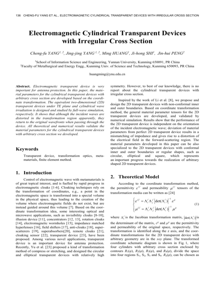
coordinate schematic diagram is shown in Fig. 1, where
four cylinders with arbitrary cross section enclosed by
contours R1(φ), R2(φ), R3(φ), and R4(φ), divide the space
into four regions S1, S2, S3 and S4. Rn(φ), can be chosen as
RADIOENGINEERING, VOL. 19, NO. 1, APRIL 2010
137
arbitrary continuous functions with period 2π, and it can be
expressed by a Fourier series as [8]
Rn ( ) Am cos(m ) Bm sin(m ) .
m0
(2)
ij ij
m 1
The coordination transformation for the transparent
devices with arbitrary geometries includes two steps [23].
Firstly, we keep the regions S1 and S4 invariant; secondly,
we compress the region S3 and S4 into region S4, and stretch
the region S2 to the region S2 and S3. The corresponding
mapping is,
r k1r k2 ,
,
A12 A2 2
AB A B
2 1
1 2
A1 B1 A2 B2
A1 B2 A2 B1
0
1
B12 B2 2
A1 B2 A2 B1
0
(11)
0
1
A1 B2 A2 B1
0
y
0.8
0.6
(3)
(4)
0.4
0.2
0
z z
A1 B1 A2 B2
A1 B2 A2 B1
(5)
where
-0.2
-0.4
k1 ( R3 ( )) /( R2 ( )) ,
-0.6
o S1
S2
S3
S4
x
R1( )
R2( )
R3( )
-0.8
k2 (1 k1 ) [ R3 ( ) R2 ( )]/[ R2 ( )] .
-1
If R3(φ) < r < R4(φ), τ = R4(φ), which corresponds to
compressive region; if R1(φ) < r < R3(φ), τ = R1(φ), which
corresponds to stretching region. The coordinate transformation equations are expressed by
x r cos( ) k1 x k2 x / x 2 y 2 ,
(6)
y r sin( ) k1 y k2 y / x 2 y 2
(7)
z z
(8)
with the Jacobi matrix and its determinant
ii [ A1 , A2 , 0; B1 , B2 , 0;0, 0,1] ,
(9)
det( ii ) A1 B2 A2 B1
(10)
R4( )
-0.5 diagram0 of the space
0.5 transformation
1
Fig.1. -1 Schematic
for the
design of arbitrary shaped 2D transparent devices.
Equation (11) gives the general expressions of the
material parameters for the 2D transparent devices with
non-conformal inner and outer boundaries. The permeability tensor is equal to the permittivity tensor. For special
case R1(φ) = t1R4(φ), R2(φ) = t2R4(φ), R3(φ) = t3R4(φ), where
ti < 1 (i = 1,2,3 and 0 < t1 < t2 < t3 < 1) represents the linear
compression ratio between the inner and outer boundaries,
equation (11) can be simplified as
xx {[r R( )(1 k1 )]2 cos 2 2 (1 k1 ) 2 P 2 cos 2
yy {[r R( )(1 k1 )]2 sin 2 2 (1 k1 ) 2 P 2 sin 2
where
2 (1 k1 )r P sin cos r 2 cos 2 }/ r [ r R( )(1 k1 )]
A1 k1 a sin cos (k2 / r ) sin 2 (b / r ) sin cos ,
xy { R( )(1 k1 )[2r R( )(1 k1 )]sin cos
A2 a cos 2 (k2 / r ) sin cos (b / r ) cos 2 ,
2 (1 k1 ) 2 P 2 sin cos
B1 a sin 2 (k2 / r ) sin cos (b / r ) sin 2 ,
B2 k1 a sin cos (k2 / r ) cos (b / r ) sin cos ,
2
a {[ R2 ( )][
d dR3 ( )
d dR2 ( )
] [ R3 ( )][
]}/[ R2 ( )]2
d
d
d
d
,
dR ( ) dR2 ( )
d
[ R3 ( ) R2 ( ]) [ 3
]}/[ R2 ( )]
d
d
d
d dR2 ( )
[ R3 ( ) R2 ( )][
] /[ R2 ( )]2
d
d
b {
Substituting (9) and (10) into (1), we can obtain the relative
permittivity and permeability tensors of the 2D transparent
device as
(12a)
2 (1 k1 )r P sin cos r 2 sin2 }/ r [r R( )(1 k1 )]
(12b)
(12c)
(1 k1 )r P(cos 2 sin 2 )}/ r [r R ( )(1 k1 )]
zz [r R( )(1 k1 )]/ r / k12
(12d)
yx xy and xz yz zx zy 0
(12e)
For the cylindrical transparent devices with regular geometric shapes such as circular, elliptical and square, the
contour equation Ri(φ) can be simplified by the procedure
illustrated in [9] to obtain the corresponding material
parameters. It means that the material parameters deduced
in this paper can be specialized to all formally designed 2D
transparent devices with conformal inner and outer
boundaries.
138 CHENG-FU YANG ET AL., ELECTROMAGNETIC CYLINDRICAL TRANSPARENT DEVICES WITH IRREGULAR CROSS SECTION
3. Simulation Results and Discussion
In this section, based on the finite element software
COMSOL Multiphysics, we make full-wave simulation on
the 2D transparent device with non-conformal inner and
outer boundaries under TE wave and cylindrical wave
irradiations, in order to validate the designed equation (11).
To show the flexibility of the proposed approach to design
cylindrical transparent device with irregular cross section,
the contour equations
(13)
R1 ( ) (12+2cos( )+sin(2 )-2sin(3 ))/320
R2 ( ) (20+2sin(2 )-3sin(5 )+5cos(7 ))/288
(14)
R3 ( ) 0.175(0.8+0.1cos( )+0.2cos(5 )+0.1sin(5 )) (15)
(16)
R4 ( ) (10+sin( )-sin(2 )+2cos(5 ))/48
are chosen as an example. Since the material parameters of
the 2D transparent device are independent on frequency, its
performance does not vary significantly with frequency.
Here, the frequency of the excitation source is set to be
2.5 GHz.
3.2 Field Distribution of the 2D Transparent
Device under Cylindrical Wave
Irradiation
Since the proposed 2D transparent device has no
symmetry in any direction, it’s necessary to study its
interaction with electromagnetic waves from different
orientations. Fig. 3(a)-(d) illustrate the electric field
distribution in the vicinity of the 2D transparent device
under cylindrical wave irradiation, where line sources with
current 10-3A/m in z direction are located at (-0.35m, 0),
(0, 0.35m), (-0.35m, -0.35m) and at the centre of the
device, respectively. From Fig. 3(a)-(c), we can see that
although the waves are distorted in the transformation
region, they recovered the original propagation status when
passing through the device. Interestingly, in Fig. 3(d) when
the line source is located at the centre of the device, i.e.,
inclosed in the structure, the wavefronts of the cylindrical
wave are perfectly recovered, as if the device does not
exist. It indicates the effectiveness of the 2D transparent
devices with arbitrary geometries in the application of
optical and electromagnetic engineering.
3.1 Field Distribution of the 2D Transparent
Device under TE Wave Irradiation
Fig. 2(a)-(d) show the electric field distributions in the
vicinity of the 2D transparent device under TE wave
irradiation. The TE plane wave has an electric polarized in
z direction with unit amplitude. In the simulation, perfect
matched layers (PML) are applied to terminate the computational domain in ±x and ±y directions. In Fig. 2(a), the
incident TE wave is from left to right along the x axis. In
Fig. 2(b), the incident wave is from upside to downside
along the y axis. In Fig. 2(c) and 2(d) the waves are irradiated with angles of 45o and -45o, respectively. It can be
clearly seen that although the waves are distorted in the
transformation region, they return to the original propagation directions and wavefronts when passing through the 2D
transparent device. The performance of the device is independent on the orientation of the incident wave.
Fig.3.
(Color online) The electric field distribution in the
computational domain for the 2D transparent device
with arbitrary geometry under cylinder wave
irradiation.
3.3 Influence of Metamaterial Loss on the
Performance of the 2D Transparent
Device
Fig.2.
(Color online) The electric field (Ez) distribution in
the computational domain of the 2D transparent
device under TE wave irradiation.
Since metamaterials are always lossy in real applications, it does make sense to investigate the effect of loss on
the transparent property of the device. The electric field in
the vicinity of the 2D transparent device with electric and
magnetic-loss tangents (tgδ) of 0.001, 0.005, 0.01 and 0.02
are displayed in panels (a), (b), (c) and (d) of Fig. 4,
respectively. As it can be seen from Fig. 4(a) and (b) that
the electric field distributions are basically undisturbed
when loss tangents of 0.001 and 0.005 are added to both
permittivity and permeability tensors of the anisotropic and
inhomogeneous materials. When the loss tangent of the
metamaterials is 0.01 or more than that, it deteriorates the
RADIOENGINEERING, VOL. 19, NO. 1, APRIL 2010
139
performance of the 2D transparent device, as shown in Fig.
4(c) and 4(d). The electric field distributions along the x
axis of the 2D transparent device with electric and magnetic-loss are shown in Fig. 5. It can be seen that for the
back-scattering region, performance of the 2D transparent
device is independent on the loss tangent of the metamaterials. The increase of loss tangent deteriorates the
performance of the 2D transparent device in the forwardscattering region of the near field. In this paper, the properties of the transparent device to TE waves are numerically
verified. Since the permeability tensor is identical to the
permittivity tensor, the responses of the transparent device
to TM waves are the duality of their response to TE waves.
Hence, the numerical results for TM cases are not included
for brevity.
device, and found that the electric field distributions of the
2D transparent devices are basically undisturbed when loss
tangent of metamaterials is less than 0.01. It is expected
that our works are helpful for designing new transparent
devices for antenna protection and contribute to more
applications in electromagnetic field engineering.
Acknowledgements
This work was supported by the National Natural
Science Foundation of China (grant no. 60861002),
Training Program of Yunnan Province for Middle-aged and
Young Leaders of Disciplines in Science and Technology
(Grant No. 2008PY031), the Research Foundation from
Ministry of Education of China (grant no. 208133), the
Natural Science Foundation of Yunnan Province (grant
no.2007F005M), and the National Basic Research Program
of China (973 Program) (grant no. 2007CB613606).
References
[1] PENDRY, J. B., SCHURIG, D., SMITH, D. R. Controlling
electromagnetic fields. Science, 2006, vol. 312, no. 5781, p.1780
to 1782.
[2] LEONHARDT, U. Optical conformal mapping. Science, 2006, vol.
312, no. 5781, p. 1777-1780.
Fig.4.
(Color online) The electric field (Ez) distributions in
the computational domains for the 2D transparent
devices with loss tangents of 0.001 (a), 0.005 (b), 0.01
(c) and 0.02(d), respectively.
Electric field distribution (v/m)
tg=0.02
tg=0.01
tg=0.005
tg=0.001
tg=0
[6] VALENTINE, J., LI, J., ZENTGRAF, T., BARTAL, G., ZHANG,
X. An optical cloak made of dielectrics. Nature Materials, 2009,
vol. 8, no. 7, p.568-571.
0
[7] ALITALO, P., TRETYAKOV, S. Electromagnetic cloaking with
metamaterials. Materials today, 2009, vol. 12, no. 3, p. 22-29.
-1
-2
[4] LEONHARDT, U., TYC, T. Broadband invisibility by noneuclidean cloaking. Science, 2009, vol. 323, no. 5910, p. 110-112.
[5] LIU, R., JI, C., MOCK, J. J., CHIN, J. Y., CUI, T. J., SMITH,
D.R. Broadband ground-plane cloak. Science, vol. 323, no. 5912,
p. 366-369.
2
1
[3] SCHURIG, D., MOCK, J. J., JUSTICE, B. J., CUMMER, S. A.,
PENDRY, J. B., STARR, A. F., SMITH, D. R. Metamaterial
electromagnetic cloak at microwave frequencies. Science, 2006,
vol. 314, no. 5801, p. 977-980.
-0.2
-0.1
0
0.1
0.2
0.3
0.4
x(m)
Fig. 5. The electric field distributions along x axis for the 2D
transparent devices with different loss tangents.
4. Conclusions
The material parameters for 2D transparent devices
with arbitrary geometries are developed. A peculiar 2D
transparent device is designed as an example. All theoretical and numerical results validate the material parameters
for the cylindrical transparent devices with arbitrary cross
section we deduced. Besides, we have investigated the
influence of metamaterial loss on the performance of the
[8] LI, C., YAO, K., LI, F. Two-dimensional electromagnetic cloaks
with non-conformal inner and outer boundaries. Optics Express,
2008, vol. 16, no. 23, p.19366-19374.
[9] LI, C., LI, F. Two-dimensional electromagnetic cloaks with
arbitrary geometries. Optics Express, 2008, vol. 16, no. 17, p.
13414-13420.
[10] WU, Q., ZHANG, K., MENG, F. Y., LI, L. W. Material
parameters characterization for arbitrary N-sided regular
polygonal invisible cloak. J. Appl. Phys. D: Appl. Phys., 2009,
vol. 42, no. 3, p. 035408.
[11] LAI, Y., NG, J., CHEN, H. Y., HAN, D. Z., XIAO, J. J., ZHANG,
Z. Q., CHAN, C. T. Illusion optics: the optical transformation of
an object into another object. Phys. Rev. Lett., 2009, vol. 102, no.
25, p. 253902.
[12] RAHM, M., SCHURIG, D., ROBERTS, D. A., CUMMER, S. A.,
SMITH, D. R., PENDRY, J. B. Design of electromagnetic cloaks
and concentrators using form-invariant coordinate transformations
140 CHENG-FU YANG ET AL., ELECTROMAGNETIC CYLINDRICAL TRANSPARENT DEVICES WITH IRREGULAR CROSS SECTION
of Maxwell’s equations. Photonics and NanostructuresFundamentals and Applications, 2008, vol. 6, no. 1, p. 87-95.
[13] YANG, J. J., HUANG, M., YANG, C. F., XIAO, Z., PENG, J. H.
Metamaterial electromagnetic concentrators with arbitrary
geometries. Optics Express, 2009, vol. 17, no. 22, p.19656-19661.
[14] CHEN, H., CHAN, C. T. Transformation media that rotate
electromagnetic fields. Appl. Phys. Lett., 2007, vol. 90, no. 24, p.
241105.
[15] GREENLEAF, A., KURYLEV, Y., LASSAS, M., UHLMANN, G.
Electromagnetic wormholes and virtual magnetic monopoles from
metamaterials. Phys. Rev. Lett., 2007, vol. 99, no. 18, p. 183901.
[16] KILDISHEV, A. V., NARIMANOV, E. E. Impedance-matched
hyperlens. Opt. Lett., 2007, vol. 32, no. 23, p. 3432-3434.
[17] RAHM, M., CUMMER, S. A., SCHURIG, D., PENDRY, J. B.,
SMITH, D. R. Optical design of reflectionless complex media by
finite embedded coordinate transformations. Phys. Rev. Lett.,
2008, vol. 100, no. 6, p. 063903.
[18] CHEN, H. Y., LUO, X. D., MA, H. R., CHAN, C. T. The anticloak. Optic. Express, 2008, vol. 16, no. 19, p.14603-14608.
[19] YANG, T., CHEN, H. Y., LUO, X. D., MA, H. R. Superscatterer:
Enhancement of scattering with complementary media. Optics
Express, 2008, vol. 16, no. 22, p. 18545.
[20] NG, J., CHEN, H. Y., CHAN, C. T. Metamaterial frequencyselective superabsorber. Optics Letters, 2009, vol. 34, no. 5,
p.644-646.
[21] LAI, Y., CHEN, H. Y., ZHANG, Z. Q., CHAN, C. T.
Complementary media invisibility cloak that cloaks objects at
a distance outside the cloaking shell. Phys. Rev. Lett., 2009, vol.
102, no. 9, p. 093901.
[22] ALÙ, A., ENGHETA, N. Cloaking a sensor. Phys. Rev. Lett.,
2009, vol. 102, no. 23, p. 233901.
[23] YU, G. X., CUI, T. J., JIANG, W. X. Design of transparent
structure using metamaterial. J. Infrared Milli Terahz Waves,
2009, vol. 30, no. 6, p. 633-641.
[24] SCHURIG, D., PENDRY, J. B., SMITH, D. R. Calculation of
material properties and ray tracing in transformation media.
Optics Express, 2006, vol. 14, no. 21, p. 9794.
About Authors ...
Cheng-fu YANG was born in Dali Yunnan, China. He
received the B.S. degree from Yunnan University. Now he
is a graduate student of Yunnan University. His research
interests are in the fields of electromagnetic computation
and research of metamaterials.
Jing-jing YANG was born in Hekou, Yunnan, China. She
received the B.S. and M.S. degrees in electric engineering
from Yunnan University, Kunming, China, in 2005 and
2007, respectively. She is now a Ph.D candidate in Faculty
of Materials and Metallurgical Engineering, Kunming
University of Science and Technology, China. Her research
interests are metamaterials, electromagnetic theory, and
wireless communication.
Ming HUANG was born in Wenshan, Yunnan, China. He
received the B.S. and M.S. degrees in electric engineering
from Yunnan University, Kunming, China, and the Ph. D
degree in microwave engineering from Kunming University
of Science and Technology, China, in 1984, 1987, and
2006, respectively. His main research interests include
wireless communication, microwave power application, and
metamaterials. In his research area, he has (co-) authored 4
books, over 70 refereed journal papers and international
conference papers. One of his research papers was
highlighted by Nature China in June, 2007.
Ji-hong SHI was born in Qing Zhou, Shandong, China.
She received the B.S. degree from Huazhong University of
Science and Technology in 1985. Her main research
interests include wireless communication, microwave
power application, and metamaterials. In her research area,
she has (co-) authored 4 books, over 20 refereed journal
papers and international conference papers.
Jin-hui PENG was born in Mojiang, Yunnan, China. He
received the B.S., M.S., and Ph.D degrees in metallurgical
engineering from Kunming University of Science and
Technology, China, in 1985, 1988, and 1992, respectively.
His research interest is electromagnetic theory and microwave metallurgy. In his research area, he has (co-) authored
4 books, over 160 refereed journal papers. He has won
many awards including the first and second Science awards
of Yunnan Province, and the Gold awards of the Scientific
and Technological Achievements of Young Chinese, etc.
