MedPhys_Supplementary_Revised2
advertisement
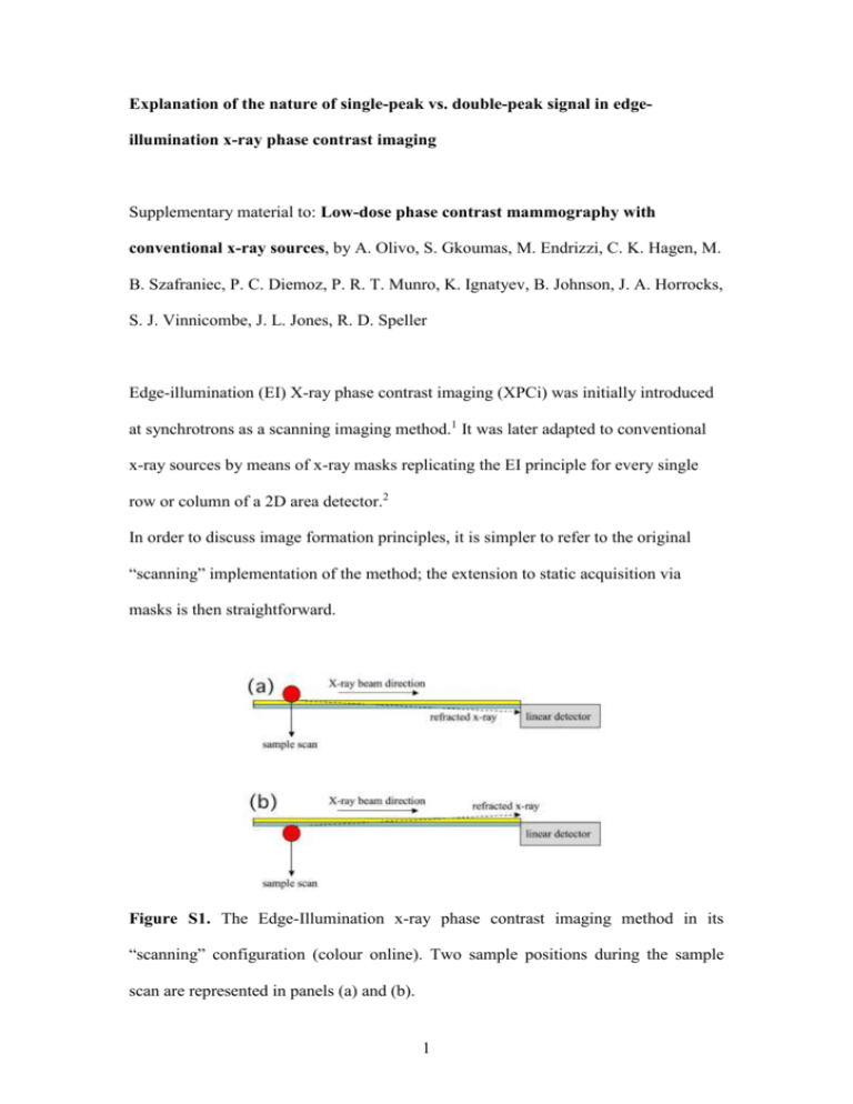
Explanation of the nature of single-peak vs. double-peak signal in edgeillumination x-ray phase contrast imaging Supplementary material to: Low-dose phase contrast mammography with conventional x-ray sources, by A. Olivo, S. Gkoumas, M. Endrizzi, C. K. Hagen, M. B. Szafraniec, P. C. Diemoz, P. R. T. Munro, K. Ignatyev, B. Johnson, J. A. Horrocks, S. J. Vinnicombe, J. L. Jones, R. D. Speller Edge-illumination (EI) X-ray phase contrast imaging (XPCi) was initially introduced at synchrotrons as a scanning imaging method.1 It was later adapted to conventional x-ray sources by means of x-ray masks replicating the EI principle for every single row or column of a 2D area detector.2 In order to discuss image formation principles, it is simpler to refer to the original “scanning” implementation of the method; the extension to static acquisition via masks is then straightforward. Figure S1. The Edge-Illumination x-ray phase contrast imaging method in its “scanning” configuration (colour online). Two sample positions during the sample scan are represented in panels (a) and (b). 1 The image formation mechanism is discussed in Figure S1. A row of pixels entering the plane of the drawing (“linear detector”) is illuminated on its top edge by a beam that is vertically thin, but as long as the linear detector itself in the direction entering the plane of the drawing. For explanatory purposes, the beam has been represented with two different colours to distinguish between the portion missing the pixel (yellow) and the one hitting it (light blue), although in practice this is a single beam. The differential phase contrast signal is created by refraction from the object or from details inside the object. These can create positive and negative peaks; however, these arise separately from the yellow and the light blue parts of the beam, respectively. The creation of a positive peak is shown in figure 1S (a). When the detail touches the upper part of the beam, x-rays that would normally miss the pixel are refracted inside it, increasing the number of counts. This situation is encountered only for the “yellow” part of the beam: since, in the absence of the sample, these photons miss the detector, they cannot be used to decrease the number of counts i.e. contribute to the creation of a negative signal. Exactly the opposite happens for the “light blue” part of the beam. These photons normally hit the detector and are thus counted: however, refraction from the object can send them outside the pixel, as shown in figure 1S (b). When this happens, the number of counts detected decreases, i.e. a negative peak is formed. Similarly to what discussed for the yellow part of the beam, these photons can only create negative peaks and cannot contribute to positive ones: in the absence of the sample, they are all counted (compatibly with the efficiency of the used detector). This means that, if the yellow part of the beam is eliminated and the detector is illuminated only by the light blue beam, a scan of the sample will result in negative 2 peaks only; conversely, if the light blue part is eliminated, the scan will only yield positive peaks. While the latter example has been reported previously,1 the situation discussed in the paper falls in the former category i.e. elimination of the beam portion falling outside the detector, leading to negative peaks only. In particular, figure 4 in the main article shows a direct comparison between the “double peak” and the “negative peak only” case. Figure S2. The Edge-Illumination x-ray phase contrast imaging method in its static, 2D configuration (colour online). Figure S2 shows the translation to the static, 2D implementation of the method obtained through x-ray masks. The plurality of beamlets created by the pre-sample mask effectively replaces the scanning, so that it is sufficient to place the sample downstream of the pre-sample mask and image it in a single shot. The beamlets have been colour-coded in yellow and light blue, with the two colours having exactly the same meaning as for figure S1. Eliminating the yellow parts of the beam therefore leads to images in which positive peaks disappear and only negative phase peaks are observed. In the embodiment discussed in this article, this has been obtained simply 3 by reducing the size of the apertures in the pre-sample mask, and appropriately positioning the two masks in such a way that the portion of each beamlet hitting the solid septa on the detector mask is negligible. More quantitative details on the image formation principles can be found in reference 3. References 1 A. Olivo, F. Arfelli, G. Cantatore, R. Longo, R. H. Menk, S. Pani, M. Prest, P. Poropat, L. Rigon, G. Tromba, E. Vallazza, and E. Castelli, “An innovative digital imaging set-up allowing a low-dose approach to phase contrast applications in the medical field,” Med. Phys. 28,1610-1619 (2001). 2 A. Olivo and R. Speller, “A coded-aperture approach allowing x-ray phase contrast imaging with conventional sources,” Appl. Phys. Lett. 91, 074106 (2007). 3 A. Olivo and R. Speller, “Image formation principles in coded-aperture based x-ray phase contrast imaging,” Phys. Med. Biol. 53, 6461-6474 (2008). 4
