Passive laminar flow
advertisement
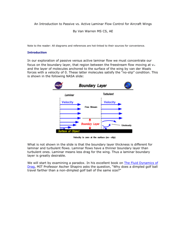
An Introduction to Passive vs. Active Laminar Flow Control for Aircraft Wings By Van Warren MS CS, AE Note to the reader: All diagrams and references are hot-linked to their sources for convenience. Introduction In our exploration of passive versus active laminar flow we must concentrate our focus on the boundary layer, that region between the freestream flow moving at v and the layer of molecules anchored to the surface of the wing by van der Waals forces with a velocity of 0. These latter molecules satisfy the “no-slip” condition. This is shown in the following NASA slide: What is not shown in the slide is that the boundary layer thickness is different for laminar and turbulent flows. Laminar flows have a thinner boundary layer than turbulent ones. Laminar means less drag for the wing. Thus a laminar boundary layer is greatly desirable. We will start by examining a paradox. In his excellent book on The Fluid Dynamics of Drag, MIT Professor Ascher Shapiro asks the question, “Why does a dimpled golf ball travel farther than a non-dimpled golf ball of the same size?” Prof. Shapiro’s example highlights the importance of understanding the nature of laminar versus turbulent fluid flow. It is also critical to understand the flight regime in which we are operating. Are we a sailplane or a fighter jet? The graph above illustrates this paradox. The golf ball is operating in a low Reynolds number environment. If golf balls were fired from guns like musket balls, smooth golf balls might travel farther. An excellent problem to study would be, “How fast would Tiger Woods have to hit a golf ball for it to lose its dimples?” It is helpful to recall the definition of Reynolds number. According to NASA GRC, the conservation of mass in three dimensions, a change in velocity in the streamwise direction causes a change in velocity in the other directions as well. There is a small component of velocity perpendicular to the surface which displaces or moves the flow above it. One can define the thickness of the boundary layer to be the amount of this displacement. The displacement thickness depends on the Reynolds number which is the ratio of inertial (resistant to change or motion) forces to viscous (heavy and gluey) forces and is given by the equation: Re vl where = density of the fluid v = freestream velocity l = characteristic dimension, for example thickness = viscosity of the fluid It is key that we recognize that a golf-ball is always operating in a “stall”, that is with a significant area of separated flow. Under normal flight conditions a wing is not operating in a stall, yet we must keep its behavior in a stall in mind for safety in design reasons. One key to understanding the golf ball case is that a turbulent boundary layer is thicker than a laminar boundary layer. However the turbulent boundary layer remains attached to the ball reducing the bluff body wake significantly. A thick boundary layer by its very nature implies more drag than a thin one. In the sphere example, the advantages of the flow remaining attached around the back of the ball outweight the gains due to laminar flow. For this reason, in compromised situations, dimples, “boundary layer trips”, “vortexgenerators” or other mechanisms are installed to insure that the flow remains attached as long as possible. The aft surfaces of some aircraft are dimpled for this reason. Most automobile sun-roofs have a trip just ahead of the sunroof to prevent low frequency rumbling due to a laminar flow field. Aircraft like the 727 have vortex generators to encourage the flow to remain attached in near-stall conditions. This along with airfoil and wing design prevent precipitous changes in lift in off-design flight configurations. Passive Boundary Layer Control - A Gloster Javelin showing three sets of vortex generators located along the outer portion of the wing You may have observed the stream of fluid on a ski boat that encounters a bump or defect in the hull. The flow aft of this is always turbulent and extends in a growing vshape that contaminates the laminar flow around it. In aircraft and racing cars a special inlet called the NASA inlet minimizes the induced turbulence from necessary penetrations of the cabin or hull. Summary Engineering is about trade-offs. If the benefits of drag reduction are outweighed by system complexity, cost, or weight, then we are forced to accept passive solutions. Active boundary layer suction is implemented at the cost of engine power, fallibility (bugs, dirt, dust), cost (holes and ducting). Active boundary layer suction turns an aircraft into an air filter, and the overhead of keeping that filter clean becomes an important aspect of the overall cost/benefit equation. Reynold’s Number A key indicator of whether the flow is likely to be laminar or turbulent is the Reynold’s number. Viscosity Passive Laminar Flow Active Laminar Flow Visualizing Flow Aerodynamic Efficiency Delaying Transition from Laminar Flow Other Considerations Pitching Moment Stability Precipitous Change in Drag and Lift Coefficients Graceful Degradation Delaying the Onset of Turbulence. Passive Laminar Flow means to insure that Active Laminar flow control Active LFC must be used to achieve laminar flow across larger distances from the leading edge. The main means of achieving active LFC is to remove a portion of the turbulent boundary layer with a suction or blowing mechanism that uses porous material, slots in the wing, or tiny perforations in the wing skin (see figure8). Figure 8: F-16 used in the LFC study NASA used F-16XL in the LFC study were modified to operate a suction system that pulled the turbulent boundary layer through a porous sheet of titanium that was the upper wing surface in the test area. Passive laminar flow Passive laminar flow can be achieved in the wing design process, but the laminar condition is normally very small in relation to the wing's cord and is usually confined to the leading edge region. The North American P-51 Mustang fighter of World War II fame had a first design of passive laminar flow wing, but laminar conditions existed for only a very short distance past the leading edge. Passive laminar flow can also be created on an existing wing by altering the cross-sectional contour of the lifting surface to change the pressure gradient. Both of these laminar conditions are called natural laminar flow.
