Fluid Properties
advertisement
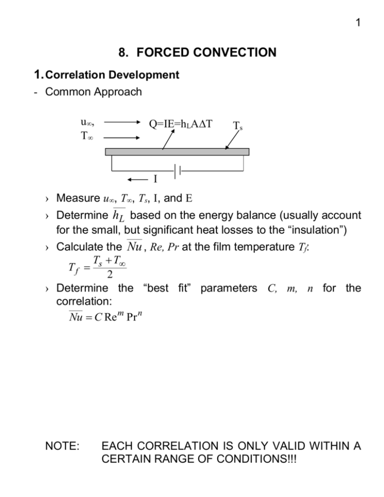
1 8. FORCED CONVECTION 1. Correlation Development - Common Approach u, T Q=IE=hLAT Ts Ts I › Measure u, T, Ts, I, and E › Determine hL based on the energy balance (usually account for the small, but significant heat losses to the “insulation”) › Calculate the Nu , Re, Pr at the film temperature Tf: T T Tf s 2 › Determine the “best fit” parameters C, m, n for the correlation: Nu C Re m Pr n NOTE: EACH CORRELATION IS ONLY VALID WITHIN A CERTAIN RANGE OF CONDITIONS!!! 2 2. Parallel Flow on a Flat Plate - Laminar Flow › Pr 0.6 5.0 x ; C f ,L Re x 1.328 Re L Pr1 / 3 t Sc1 / 3 m (7.19; 24; 28) (7.30) Nu L hx L 0.664(Re L )1 / 2 (Pr)1 / 3 k (7.31) ShL hm L 0.664(Re L )1 / 2 ( Sc)1 / 3 D AB (7.32) › Pr 0.05 and Pex > 100 Nu x 0.565 Pe1x / 2 (7.33) where: Pex = Peclet Number (= RexPr) › Pex > 100 (Churchill and Ozoe Formula) Nu x 0.3387 Re x1 / 2 Pr1 / 3 [1 (0.0468 / Pr) (7.34) 2 / 3 1/ 4 ] - Turbulent Flow 0.37 x Re x 1 / 5 ; C f , x 0.0592 Re x 1 / 5 t m Rex 107 (7.36) (7.35) Nu x 0.0296 Re x 4 / 5 Pr1 / 3 0.6<Pr <60 (7.37) Shx 0.0296 Re x 4 / 5 Sc1 / 3 0.6<Pr <300 (7.38) - Mixed BL Conditions If transition occurs in the middle of the plate, both laminar and turbulent flow must be considered! hL 1 0xc hlam dx xL 0 htur dx c L See Eqs. 7.39 to 43 3 - Uniform Surface Heat Flux › Laminar flow Pr 0.6 Nu x 0.453 Re1x/ 2 Pr1 / 3 › Turbulent flow 0.6 Pr 60 Nu x 0.0308 Re 4x / 5 Pr1 / 3 - Unheated Starting Length Laminar flow Nu x Nu x 0 3 / 4 1/ 3 [1 ( / x) ] Turbulent flow Nu x Nu x [1 ( / x) 0 9 / 10 1 / 9 ] 3. Flow around Cylinders - Drag Coefficient Eq. 7.54 + Fig. 7.8 - Heat coefficient, hL › Hilpert Formula (Eq. 7.55b + Tables 7.2 and 7.3) Note: Evaluate the fluid properties at Tf › Zhukauskas Formula (Eq. 7.56 + Table 7.4) Note: Evaluate the fluid properties at T › Churchill and Bernstein Formula (Eq. 7.57) Note: Evaluate the fluid properties at Tf 4. Flow around Spheres Similar idea for cylinders See Eq. 7.59 Evaluate the fluid properties at T Summary of hL correlations for external flows: Table 7.9 4 5. Flow across Tube Banks See Eqs. 7.61 to 7.68 6. Pipe and Tube Flow - Basic Fluid Dynamics ReD,c ~ 2,000 to 4,000 › Entry Length Laminar flow: Turbulent flow › Velocity Profile Laminar flow: Turbulent flow › Friction Coefficient Laminar flow: Turbulent flow x fd , h / D lam 0.05 Re D 10 x fd , h / D 60 turb u 1 (r / r ) 2 o u0 u 1 (r / r ) 0.143 o u0 f 64 ; Re D Cf Moody diagram f 4 5 - Heat Transfer in Pipe Flow › Newton’s Law of Cooling q "s h(Ts Tm ) where: Note: Tm = mean temperature in the pipe 1) Tm is defined in terms of the energy transported across the pipe section as: Tm Ac ucvTdAc 2 2 0ro uTrdr m cv u m ro 2) Tm varies with the flow distance x 3) In practice, Tm (Tm, i Tm, o ) / 2 › Energy Balance Equation For incompressible liquids and ideal gases within fully developed region: m c p dTm q "s ( Pdx) h(Ts Tm )( Pdx) or dTm q "s P h(Ts Tm ) P dx m c p m c p where: P = perimeter of the cross-section. › Constant Surface Heat Flux, q "s dTm q "s P const dx m c p " Tm ( x) Tm, i q s P x m c p › Constant Surface Temperature, Ts dTm d (Ts Tm ) h(Ts Tm ) P dx dx m c p Integrating it from the inlet to outlet, TTo i d (Ts Tm ) P 0L hdx (Ts Tm ) m c p 6 (Ts Tm, o ) To exp PL hL (Ts Tm, i ) Ti m c p Total heat transfer is: c p (Tm, o Tm, i ) m c p (Ti To ) hL ( PL)Tlm qconv m where: Tlm To Ti ln( To / T ) - Convection Correlations › Fully Developed, Laminar Flow q"s const Nu D hD 4.36 Nu D k hD 3.66 k Ts const › Fully Developed, Turbulent Flow See Eqs. 8.60 to 8.63 Note the fluid properties should be evaluated at Tm › Entry Length, Laminar Flow with See Eqs. 8.56 to 8.57 › Noncircular Tubes Replace D with hydraulic diameter Dh Dh where: 4 Ac P Ac = flow cross-section P = wetted perimeter Summary of hL correlations for internal flows: Table 8.4
