DOC - Waterous
advertisement
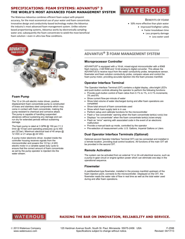
SPECIFICATIONS: FOAM SYSTEMS: ADVANTUS® 3 THE WORLD’S MOST ADVANCED FOAM MANAGEMENT SYSTEM The Waterous Advantus combines efficient foam output with pinpoint accuracy, for the most economical use of your water and foam concentrate. Innovative design and conductivity-based technology makes the Advantus the industry’s most advanced foam management system. Unlike volumebased proportioning systems, Advantus works by electronically sampling water and, subsequently the foam concentrate to wield the most beneficial foam solution—even in ultra low-flow conditions. BENEFITS OF FOAM 50% more effective than plain water Improved firefighter safety Faster knockdown time Less property damage Less water used ADVANTUS® 3 FOAM MANAGEMENT SYSTEM Microprocessor Controller ADVANTUS® is equipped with a 16-bit, mixed-signal microcontroller with a 60kB flash memory, 2 kB RAM and 12-bit analog to digital converter. This allows the ADVANTUS to receive input from the water conductivity probe, temperature sensor, flowmeter and foam solution conductivity probe, compare values and control the foam pump motor, providing accurate injection into the foam process manifold. Operator Interface Terminal Foam Pump The 12 or 24-volt electric motor driven, positive displacement foam concentrate pump is constructed of brass and stainless steel components which may come in contact with foam concentrate, making the pump resistant to chemical and corrosive attack. The pump is capable of handling suspended abrasives without sustaining any damage and can run dry for extended periods without sustaining damage. The foam pump is rated at 3 GPM @ 150 psi (11.3 l/min @ 10 bar) and operating pressures up to 450 psi (32 bar). Maximum electrical load of 40 amps @ 12 VDC or 21 amps @ 24 VDC. A pump motor electronic driver, located inside the controller housing receives signals from the microcontroller and powers the 1/2 hp (.4 kW) electric motor in a variable speed duty cycle to ensure that the correct amount of foam concentrate as set by the pump operator is injected into the water stream. The Operator Interface Terminal (OIT) contains a digital display, ultra-bright LED's and push-button controls allowing the operator to perform the following functions: Provide push-button control of foam ratios from 0.1% to 1%, in 0.1% increments; 3% and 6% Show current flow-per-minute of water Show total volume of water discharged during and after foam operations are completed Show total amount of foam concentrate used Show which foam supply tank is in use Perform setup and calibrate functions for the microcontroller Flash a “low concentrate” warning when the foam concentrate tank(s) run(s) low Displays “no concentrate” when the foam concentrate tank(s) is/are empty Flash an “error” warning with associated code in the event of an electronic malfunction Provide a manual back-up mode, controlled by the operator Pre-selection of measurement units: U.S. Gallons, Imperial Gallons or Liters Dual Operator Interface Terminals (Optional) Optional second Operator Interface Terminal OIT) can be connected and installed in a remote location, providing dual control locations. All functions of the main OIT will be provided in the second OIT. Remote Activation The system can be activated from an external 12 or 24-volt electrical source, such as a pump-in-gear circuit or engine ignition power which can eliminate one step in the operational sequence. Flowmeter A paddlewheel-type flowmeter, installed in the process manifold upstream of the foam injection point, connects to the microcontroller. Displayed on the OIT, the flowmeter reads the water rate of flow in real time as well as the total water used during and after foam operations. RAISING THE BAR ON INNOVATION, RELIABILITY AND SERVICE. 2013 Waterous Company www.waterousco.com 125 Hardman Avenue South, South St. Paul, Minnesota 55075-2456 USA Specifications subject to change without notice. F-2598 Revised: 04/17/13 SPECIFICATIONS: FOAM SYSTEMS: ADVANTUS® 3 Control Cables and Connectors The cables for interconnection of the control unit, OIT, conductivity sensors and flowmeter shall be electrically shielded to prevent radio frequency or electro-mechanical interference. Low Tank Level Switch (Optional) A low tank level float switch shall be installed in each foam concentrate tank and connected to the control unit to alert the operator to low foam supply conditions. Dual Tank Selector (Optional) When two types of foam concentrates are to be used, an (optional) dual tank transfer system can be installed to provide rapid transfer of the foam concentrate source. The digital computer control display interfaces with the transfer system; provides dual foam calibration and displays separate totals for each foam concentrate used. The electrically-actuated dual tank system provides dual foam tank switching via a 3-position rocker switch located on the pump operator's panel. Indicator lights on the switch housing as well as the OIT indicate which tank is being used. The dual tank transfer system will also provide a clean water flush of the foam concentrate pump and piping to prevent mixing of incompatible foam concentrates. The system is installed to automatically read the low tank sensor for whichever foam tank is in use. The controller automatically defaults to the preset mix ratio and foam concentrate total used for the selected tank. The electric valve assembly includes an electrically actuated 5-port ball valve with a valve body of all brass construction and the valve ball of stainless steel. The actuator is powered by a 12 or 24-volt gear motor that is electronically controlled. When the selector is changed from one tank to the other, the valve automatically moves to the flush mode prior to moving to the selected tank. Since various foam concentrates require varying flush times, it is the pump operator's choice as to length of the flush cycle. Process Manifold - 2”, 2.5” or 3” ID The foam system process manifold, constructed of stainless steel with Victaulic groove connections provided at each end of the manifold for connection to the apparatus plumbing. The process manifold includes an incoming water conductivity probe, paddlewheel flowmeter, foam injection check valve, Akron Brass waterway check valve and foam solution conductivity probe. An Akron full-flow brass body check valve in the foam process manifold waterway prevents foam contamination of fire pump and water supply. A brass and stainless steel check valve provided in the foam concentrate line at the foam injection point to prevents water backflow into the foam supply reservoir(s). Stainless steel conductivity probes include gap spacers and a reverse charge feature to prevent build-up of deposits on the probe surfaces. The process manifolds, with all associated components installed, have the following flow ratings at 150 psi: 2” ID - 400 GPM (Standard) 2.5” ID - 750 GPM (Optional) 3” ID - 1250 GPM (Optional) CAFSystem Support The Advantus® is equipped with PC-Connectivity which allows a qualified technician to perform upgrades, diagnostics and monitor system functions in real-time. The system can also be remotely monitored using any PC with Internet access, allowing technicians to easily connect to the Waterous dedicated website to assure proper operation and to update the system software by uploading new features and functions as they become available. 2013 Waterous Company www.waterousco.com System Components - Standard Components of the complete foam system supplied by Waterous include: Operator interface terminal Pump module with electric motor/motor driver and microcontroller unit Foam concentrate strainer WYE Strainer Shielded electrical cables for connection of all electronic components Process manifold - 2” ID - with flowmeter and associated components as specified Installation and operation manuals are provided for the unit along with a copy of the warranty policy. The system must be installed and serviced by an authorized Waterous OEM or service center. System Components - Optional Process manifold - 2.5” or 3” ID - with flowmeter and associated components as specified Low level tank switch Electrically actuated dual tank valve (if more than one tank) with flush system and panel mounted control switch System diagram and rating placards (per NFPA 1901) for pump panel mounting Installer Supplied Items The Advantus 3 system includes the major components required for installation with the exception of the following which are to be supplied by the installer: 1. Foam Concentrate Supply Line(s) Hose(s) and fittings that run from the foam tank to the foam pump inlet should be a minimum of 3/4” inside diameter, depending upon the viscosity of the foam concentrate(s) to be used. Hose and fittings must be rated for a minimum of 23 inches (584.2 mm) Hg of vacuum and 50 psi (3 bar) of pressure. The hose and fittings must be made of corrosion resistant material and be compatible with the foam concentrates to be used. Foam supply hose shall have a clear wall as required by NFPA to allow viewing of foam priming operations. 2. Foam Concentrate Discharge Line Hose(s) and fittings that are routed from the foam pump to the foam injection check valve should be a minimum of 1/2” inside diameter and have a rated working pressure of at least 450 psi (32 bar). If the high pressure option is selected, the rated working pressure of the hose and fittings shall be at least 600 psi (41 bar). The foam discharge hose and fittings must be made of corrosion resistant material and be compatible with the foam concentrates to be used. 3. Foam Concentrate Tank(s) Foam concentrate tank(s) shall be supplied that suit the application and needs of the end user. The foam concentrate tank(s) should meet the minimum requirements as published in the applicable NFPA apparatus standards. 4. Electrical Supply Electrical wiring and circuit protection must be supplied and connected to the apparatus master electrical system as described in the installation manual. Warranty The system shall have a two-year limited manufacturer's warranty. 125 Hardman Avenue South, South St. Paul, Minnesota 55075-2456 USA Specifications subject to change without notice. F-2598 Revised: 04/17/13


