The Ladder Diagram - Purdue University Calumet
advertisement

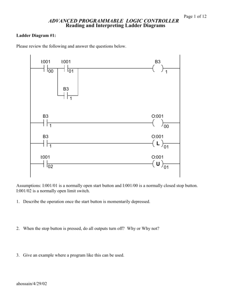
Page 1 of 12 ADVANCED PROGRAMMABLE LOGIC CONTROLLER Reading and Interpreting Ladder Diagrams Ladder Diagram #1: Please review the following and answer the questions below. I:001 00 I:001 B3 01 1 B3 1 B3 O:001 1 B3 00 O:001 1 I:001 02 L 01 O:001 U 01 Assumptions: I:001/01 is a normally open start button and I:001/00 is a normally closed stop button. I:001/02 is a normally open limit switch. 1. Describe the operation once the start button is momentarily depressed. 2. When the stop button is pressed, do all outputs turn off? Why or Why not? 3. Give an example where a program like this can be used. ahossain/4/29/02 Page 2 of 12 Ladder Diagram #2: Please review the following and answer the questions below. SUB Subtract Source A Source B Dest N7:0 10 N7:1 DIV Divide Source A Source B Dest N7:1 2 N7:2 ADD Add Source A Source B Dest N7:2 5 N7:3 A. If the value located at N7:0 is 12, what is the resultant value at N7:3? B. If the value located at N7:3 is 80, what was the value at N7:0? C. If the value located at N7:2 is 30, what was the values at N7:0 and N7:1, and what is the value at N7:3? ahossain/4/29/02 Page 3 of 12 Ladder Diagram #3: Fig. 2 Refer to Fig. 2 to answer question 2a through 2e 2a) What is the starting sequence of the motor, M1, M2 and M3 ? 2b) From the time the START SWITCH is pressed, how long does it take before the last motor is ON ? 2c) How long is the delay between the starting of M1 and M2 ? 2d) How long is the delay between the starting of M1 and M3 ? 2e) How long is the delay between the starting of M2 and M3 ? ahossain/4/29/02 Page 4 of 12 Ladder Diagram #4 Please review the following program and answer the questions. TON Timer On Delay Timer Time Base Preset Accum T4:0 DN T4:0 1.0 5 0 CTU T4:0 Count up DN Counter C5:1 Preset 100 Accum 0 LES Less Than O:001 Source A C5:1.ACC Source B 3 01 LIM Limit Test Low Limit 3 Test C5:1.ACC High Limit 7 O:001 02 GRT Less Than O:001 Source A C5:1.ACC Source B 7 1. If C5:1.ACC is equal to 3, what happens? 2. How long is it before O:001/02 turns on and how long is it on? 3. When is the done bit set on counter C5:1? ahossain/4/29/02 03 Page 5 of 12 Ladder Diagram #5: In the following ladder program, what would be the content of B3:20 when the content of the Accumulated Value Word of counter C5:0 is equal to the content of N7:10 for the above ladder program? Given: Accumulated Value of the Counter C5:0 = 100 and N7:10 = 100 Given: B 3:15 = 000011112 and B3:16 = 001100112 ahossain/4/29/02 Page 6 of 12 Ladder Diagram #6: Refer to Fig. 3 to answer question 3a. Fig. 3 3a) The OTE instruction (O:001/07) will be energized if the content of N7:1 is equal to what? Refer to Fig. 4 to answer question 3b and 3c. Fig. 4 3b) The OTE instruction (O:001/07)will be energized if the content of F8:0 is equal to what? 3c) If the content of F8:0 is 23.567, what will happen to the output O:001/07? ahossain/4/29/02 Page 7 of 12 HOW TO WRITE LADDER PROGRAM? Problem #1: Problem Description Fig. 1 shows a main conveyor with a diverter gate for defective parts to be fed onto a rejection conveyor. A camera vision sensor system is used to inspect the work-piece. If a work-piece fails inspection, the vision sensor will energized the diverted gate and the parts is routed onto the Reject Conveyor. Proximity switch #2 is used to sense the number of rejected work-piece. Another proximity switch, #1, is used to sense the total number of work-piece on the main conveyor before it passing the vision sensor system. The system also have a normally open start switch and a normally closed stop switch. Both the start and stop are instantaneous contact switches. Write a ladder program to count the number of rejected work-piece, good work-piece, and total number of work-piece inspected. The addresses of 120VAC input and output devices are listed as below. If you want to used more input and output devices for the purpose of controlling the system, list out the device description and its address. I:001/00 I:001/01 I:001/02 I:001/03 I:001/04 O:001/00 - Input from vision sensor - Normally open start switch - Normally closed stop switch - Proximity switch #1 - Proximity switch #2 - Diverter gate Fig. 1 ahossain/4/29/02 Page 8 of 12 Solution: Step #1: Read the problem twice. You must understand the problem thoroughly before start working on the solution. Step #2: Understand the logical relationship among inputs and outputs. Step #3: Draw a block diagram showing all the inputs and outputs. Proximity Sensor #1 Proximity Sensor #2 Conveyor System Controller Diverter Gate Vision Sensor Step #4: Write down description of all inputs and outputs and their source. Input 1: 120V AC normally open contact (NO) from Proximity Sensor 1 Input 2: 120V AC normally open contact (NO) from Proximity Sensor 2 Input 3: 120V AC normally open contact (NO) from Vision Sensor. Output: 120V AC normally reenergized state, Diverter Gate activation solenoid. Logical Relationship Proximity Sensor 1 must trigger a retentive counter counting up (CTU), Counter 1 Proximity Sensor 2 must trigger a retentive counter counting up (CTU), Counter 2 Work-piece passed equal to the difference between the counter reading of Counter 1 and Counter 2. Operation must be started and remained active for the proximity system, belt conveyors, and vision system. Conveyor motor should run continuously. Start switch ON is the condition for starting conveyor belt, diverter gate. Conveyor running & Proximity Sensor1activate – count-up for total parts Conveyor running & Proximity Sensor2activate – count-up for total rejected parts Start switch ON – compute for good parts Activate Stop switch will stop the conveyor only without resetting the counter. Locked reset switch will reset the counter. ahossain/4/29/02 Page 9 of 12 The Ladder Diagram ahossain/4/29/02 Page 10 of 12 Problem #2: Problem Description Figure 1 below shows a system which stacks metal plates in a group of tens. Conveyor#1 carries the metal plates to be stacked onto conveyor#2. The lighter detector detects the metal plates as it falls from conveyor#1 to conveyor#2. Every time a metal plate from conveyor#1 breaks the detector’s light beam it produces a logic 1 (120V AC) Conveyor#2 moves for five seconds (one position) only after it stacks 10 plates. When conveyor#2 moves conveyor#1 must not move. To initiate and stop the system there are two normally open (NO) momentary contact switches. Write a ladder program using PLC 5 instruction sets to operate the system. The addresses of 120 VAC input and output devices are listed below. If you want to use more input and output devices for the purpose of controlling the system, list the device and its address below with other device addresses. I:001/00 - Light detector I:001/01 - Normally open start switch I:001/02 - Normally closed stop switch O:001/00 - C1 relay to turn on motor 1 to run conveyor #1 O:001/01 - C1 relay to turn on motor 1 to run conveyor #2 ahossain/4/29/02 Page 11 of 12 Solution: Step #1: Read the problem twice. You must understand the problem thoroughly before start working on the solution. Step #2: Understand the logical relationship among inputs and outputs. Step #3: Draw a block diagram showing all the inputs and outputs. Lighter Detector Stacking Conveyor Controller Counter (Internal Input) Conveyor #2 Motor Conveyor #1 Motor Step #4: Write down description of all inputs and outputs and their source. Input 1: 120V AC normally open contact (NO) from Proximity Sensor 1 Input 2: 120V AC normally open contact (NO) from Proximity Sensor 2 Input 3: 120V AC normally open contact (NO) from Vision Sensor. Output: 120V AC normally reenergized state, Diverter Gate activation solenoid. Logical Relationship Light detector: Every time the light detector beam is interrupted a count-up(CTU) instruction is going to count forward. The counter must be a retentive counter. Conveyor system#1 is running always except when conveyor system#2 is running for 5 second. Conveyor system#2 is running for 5 second and is adjustable depending on the dynamics of the manufacturing process. The five second timer can be done by a TON (Time-On-Delay instruction. CTU retentive timer with light detector system counts up to ten and trigger the timing of the conveyor#2 system. When the conveyor#2 completes its 5 second run the program goes back to Rung#1 and also RESETs the CTU counter for next batch of 10. ahossain/4/29/02 Page 12 of 12 ahossain/4/29/02 Page 13 of 12 Ladder Diagram #7: The following is segment of a ladder program that is transferring analog data from Analog Input Module to Analog Output Module by using a BTR and BTW instruction. Answer the following questions by referring the ladder program segment. ahossain/4/29/02 Page 14 of 12 5a) Which channel the analog input data is connected? 5b) Through which channel the analog output data is going output? 5c) What is the address of the Error Bit of the BTW instruction that is associated with the Analog output module? 5d) Are these I/O modules are located in the same rack as the processor module? ahossain/4/29/02


