18th European Symposium on Computer Aided Process Engineering – ESCAPE 18
Bertrand Braunschweig and Xavier Joulia (Editors)
© 2008 Elsevier B.V./Ltd. All rights reserved.
Modelling and simulation of a membrane
microreactor using computational fluid dynamics
Paris Chasanis,a Eugeny Y. Kenig,a Volker Hessel,b Stefan Schmitt b
a
University of Dortmund, Department of Biochemical and Chemical Engineering, EmilFigge-Str. 70, 44227 Dortmund, Germany
b
Institut für Mikrotechnik Mainz GmbH, Carl-Zeiss-Strasse 18-20, 55129 Mainz,
Germany (bitte nach Ihren Wünschen anpassen)
Abstract
In this paper, the effect of miniaturisation and inlet velocity variation on the
performance of a membrane microreactor is studied numerically. The microreactor
consists of a reaction channel, in which the water gas shift reaction takes place, and a
permeate channel, in which the permeating hydrogen is swept away. These channels are
separated by a selective palladium membrane. A 3D CFD model is developed to
account for hydrodynamics, mass transfer, chemical reaction and permeation through
the membrane. It is found that reactor miniaturisation significantly improves hydrogen
yield and recovery. Furthermore, the reaction channel feed velocity is found to exert
remarkable influence on reactor performance, whereas the impact of the sweep gas inlet
velocitiy can be considered as less important. However, the latter cannot be neglected,
and thus, both channels have to be considered simultaneously.
Keywords: membrane microreactor, mass transfer, steam reforming, water gas shift
reaction, CFD
1. Introduction
In recent years, chemical micro processes have attracted significant interest of both
chemical process industry and science [1]. These processes occur in equipment with
dimensions at micrometer and sub-millimeter scale. As a consequence, high surface
areas per unit volume and small diffusion paths are achieved resulting in increased mass
transfer rates.
Membrane-based microreactors are an important class of micro devices combining
reaction and separation inside one single shell [2]. Among a large variety of
applications, selective separation of hydrogen by means of palladium membranes seems
to be especially promising [3]. Due to the high selectivity of palladium membranes,
hydrogen can be separated with purity sufficient for its further use in micro fuel cells
[3].
In this work, the water gas shift reaction (WGS) accompanied by a removal of H2 from
a reformate gaseous mixture of CO, CO2, H2O and CH4 in a membrane microreactor is
investigated numerically. The reaction is represented by
2
P. Chasanis et al.
CO2 H2 , H0R 41, 2kJ / mol
CO H2 O
(1)
The reactor consists of a reaction channel and a permeate channel, which have a
rectangular cross-section and the same dimensions. The WGS takes place at the bottom
and at the side walls of the reaction channel coated with Pt/CeO2 catalyst. At the top of
the reaction channel, a palladium-based membrane (77%Pd-23%Cu) is placed for the
selective removal of the produced hydrogen. The hydrogen permeating through the
palladium membrane is swept away by a water vapour stream in the permeate channel.
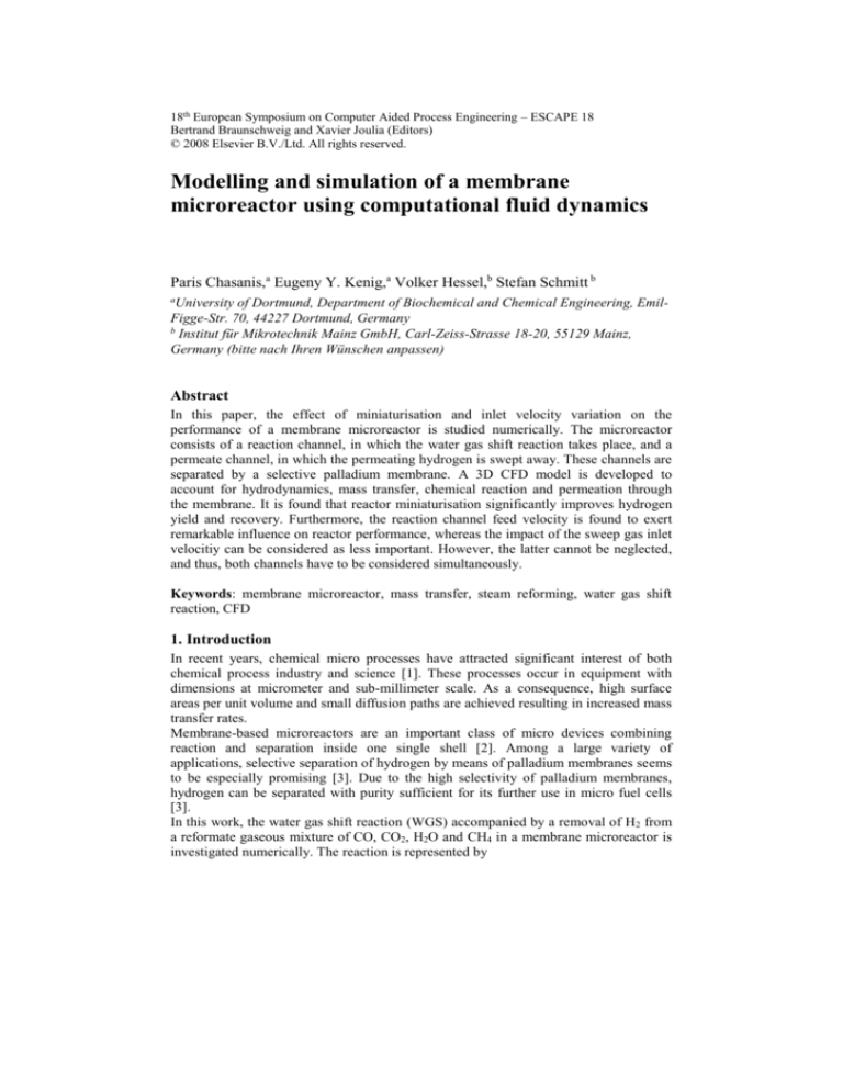
Figure 1 illustrates the configuration of the microreactor under study.
Water vapour
Membrane
Steam reformate
Catalyst
Fig. 1: The microreactor configuration: permeate channel (above) and reaction channel (below);
the catalyst and membrane surfaces are shown separately.
A 3D model was developed and applied to carry out intensive studies on the influence
of miniaturisation on reactor performance. Furthermore, the impact of the reformate
and the sweep gas velocity on the reactor behaviour is examined. The reformate
composition used in all studies (in mass percentages) is: H2 (8.9%), H2O (35.1%), CO
(29.6%), CO2 (25.1%) and CH4 (1.3%).
2. Mathematical model
The flows in both microchannels are laminar which is reflected by low Reynolds
numbers. Furthermore, ideal gas behaviour is assumed. Under isothermal and steadystate conditions, the transport phenomena in the considered microreactor can be
described by the conservation equations of overall mass, momentum and species, which
read as
u 0
(2)
uu p g u
(3)
u C D C
(4)
A no-slip boundary condition was applied at all walls, whereas inlet velocities and oulet
pressures were defined for both channels.
Hydrogen permeation molar flux through membranes can be described by the following
expression [2]:
Modelling and simulation of a membrane microreactor using CFD
JM
kM
( pHn 2 ,R pHn 2 ,P )
3
(5)
where k M is permeability, is membrane thickness pH2 ,R and pH2 ,P are partial
pressures of hydrogen in the reaction and permeate channels, respectively. The
exponent n can range from 0.5 (Sievert’s law) to 1 (Fick’s law). We experimentally
determined that the membrane under study obeys Fick’s law under the conditions
studied.
By introducing permeance K M
KM
kM
(6)
equation (5) transforms to
J M K M ( pHn 2 ,R pHn 2 ,P )
(7)
To describe the reaction kinetics, we applied the approach suggested by Keiski et al. [4],
who investigated the reaction kinetics of the WGS over a CuZnO/Al 2O3 catalyst:
0.78
rCO k1 cCO
cH0.15
( 1 )
2O
where
is reversibility factor of the reaction,
(8)
cCO2 cH 2
cH 2 O cCO KT
, and KT is
equilibrium constant. The rate constant k1 depends on temperature according to
Arrhenius’ law.
E
k1 k0 exp A
RGT
(9)
where k0 is pre-exponential factor, E A is activation energy and RG is gas constant.
Due to the considerably higher activity of the Pt/CeO2 catalyst compared to the
CuZnO/Al2O3 catalyst, the reaction rate was assumed to be of one order of magnitude
higher [5].
3. Implementation
The set of non-linear partial differential equations described in the previous section is
solved by means of the commercial CFD tool CFX® (ANSYS Inc) , which is based on
4
P. Chasanis et al.
the finite volume element method. For the discretisation of the advection terms, a high
resolution scheme is used. The hexagonal grids are generated using ICEM CFD®
(ANSYS Inc).
A set of Fortran subroutines is developed to link grid cells on both sides of the
membrane and to implement conjugate boundary conditions according to equation (7).
In this way, local driving forces and permeation fluxes through the membrane are
calculated accurately.
4. Results and discussions
4.1. Effect of miniaturisation on the reactor performance
In order to determine the impact of miniaturisation, five geometrically similar
microreactors (each consisting of a reaction and a permeate microchannel with identical
dimensions separated by a palladium-based membrane) with different cross-sectional
diameters are taken into consideration. Table 1 summarises the dimensions of the
considered microchannels:
Table 1. Dimensions of the microchannels under study
Microreactor
Height [µm]
Width [µm]
Micro-1
Micro-2
Micro-3
Micro-4
Micro-5
250
500
750
900
1250
300
600
900
1200
1500
Cross-section
diameter [µm]
272.73
545.45
818.18
1090.91
1363.64
Length [µm]
5000
10000
15000
20000
25000
The temperature is 300 °C, whereas the catalyst density is 0.04 kg/m² for all five
microreactors.
The inlet velocities, which are equal in both channels for each microreactor
configuration, range from 0.1 to 0.5 m/s and provide identical residence times. The inlet
stream in the reaction channel has the reformate composition given above, while the
sweep gas stream flowing into the permeate channel consists exclusively of water
vapour. Finally, the pressure difference between the reaction and the permeate side is 1
bar for each microreactor. The permeance of the palladium membrane was
experimentally determined and is equal to 1.95 10-9 mol m-2 s-1 Pa-1.
Figure 2a illustrates the concentration profiles of the five species in the reaction channel
and of hydrogen mass fraction in the permeate channel along the channel length of
Micro-3. Hydrogen is continuously transferred from the reaction channel into the
permeate channel resulting in a gradual hydrogen mass fraction increase in the latter.
Despite the hydrogen production on the catalyst, the hydrogen mass fraction in the
reaction channel decreases, which shows that the permeation rate through the membrane
is higher than the reaction rate of the WGS under the applied conditions. As expected,
mass fractions of both reactands (H2O and CO) decrease, whereas CO2 mass fraction
continuously grows. The mass fraction of CH4, which does not take part in the WGS,
hardly changes. The simulations were also performed for five microreactors consisting
exclusively of one reaction channel with the same dimensions (cf. Table 1)
Modelling and simulation of a membrane microreactor using CFD
a
5
b
1.0
0.7
0.9
0.6
0.8
0.7
CO2
0.6
0.4
[-]
mass fractions [-]
0.5
0.3
0.4
H2O
0.2
CO
H2
0.1
yield without hydrogen removal
0.2
yield with hydrogen removal
H2-recovery
0.0
0
0
0.3
0.1
H2(permeate)
CH4
0.5
0.002
0.004
0.006
0.008
0.01
channel length [m]
0.012
0.014
0.016
0
200
400
600
800
1000
1200
1400
1600
cross-section diameter [µm]
Fig. 2: Mass fractions of the five species in the reaction channel and of hydrogen mass fraction in
the permeate channel along the channel length of Micro-3 (a); impact of miniaturisation on
reactor performance (b)
Clearly, in these configurations, no hydrogen is transferred through the membrane.
Figure 2b gives a comparison between the achieved total hydrogen yield for both
configurations. In both cases, the yield is increased by reducing the channel dimensions.
This can be explained by the increase of the surface area per volume of catalyst.
However, the yields achieved with the simulataneous removal of hydrogen from the
reaction channel are larger than those achieved without hydrogen removal for all
microreactor dimensions studied. Obviously, the thermodynamic equilibrium of the
WGS is shifted to the product side by hydrogen separation. In fact, the difference
between the achieved yields steadily increases with decreasing microreactor dimensions
indicating the growing impact of the hydrogen removal. This is also reflected by the
increased hydrogen recovery, which is defined as the ratio of permeated hydrogen to the
total produced hydrogen.
4.2. Effect of inlet velocities on the reactor performance
The impact of the inlet velocities is investigated in two sudies on the basis of Micro-2:
in the first one, the reformate inlet velocity is varied between 0.008 and 5 m/s, whereas
in the second study, the sweep gas inlet velocity is changed in the range between 0.001
and 5 m/s. While changing the respective velocities, all the others conditions remain
unchanged as they are given in the previous section. The results of both studies are
illustrated in Figure 3. Figure 3a shows a significant influence of the reformate inlet
velocity on the hydrogen yield and on the hydrogen recovery. By decreasing the
reformate inlet velocity, the residence time in the reaction channel is increased leading
to increasing amounts of produced and permeated hydrogen and thus to higher yields
and hydrogen recovery. On the other hand, the reduction of the sweep gas inlet velocity
leads to higher hydrogen partial pressures in the permeate channel. Hence, the driving
force according to equation (7) is reduced resulting in lower permeate fluxes and,
consequently, in lower yields and hydrogen recovery. Figure 3b shows a lower
influence of the sweep gas inlet velocity on the reactor performance compared to the
reformate inlet velocity. However, this effect is not negligible.
6
P. Chasanis et al.
b
1.0
1
0.9
0.9
0.8
0.8
0.7
0.7
0.6
0.6
[-]
[-]
a
0.5
0.4
0.4
0.3
0.2
0.1
0.5
0.3
yield
yield
0.2
0.1
H2-recovery
0.0
0.001
0.01
0.1
velocity [m/s]
1
10
0
0.001
H2-recovery
0.01
0.1
1
10
velocity [m/s]
Fig 3: Impact of the reformate inlet velocity on reactor performance (a) ; impact of the sweep gas
inlet velocity on reactor performance (b)
5. Concluding remarks
In this work, a 3D CFD model is developed in order to capture hydrodynamics and
mass transfer in a membrane micro reactor consisting of a reaction channel and a
permeate channel. A particularity of this model is a coupled consideration of both
channels. By means of Fortran routines, the local driving forces are calculated
accurately, which enables concentration profiles in both channels and thus the actual
reactor performance to be exactly determined.
By decreasing the reactor dimensions, the reactor performance significantly improves as
a result of increasing catalyst and membrane surface per volume.
The impact of the reformate inlet velocity is found to be remarkable, whereas the sweep
gas inlet velocity has a lower influence. However, in the velocity range under
consideration, the achieved yields vary between 0.83 and 0.92 and the hydrogen
recovery between 0.18 and 0.4. This indicates that the effect of sweep gas inlet velocity
cannot be neglected and justifies the need to take both channels into consideration.
In the future, the impact of other process parameters (e.g. temperature, catalyst amount,
inlet concentrations) should be examined. Furthermore, the model should be extended to
describe nonisothermal conditions.
References
[1]. V. Hessel, S. Hardt, H. Löwe, 2005. Chemical micro-process engineering, Wiley-VCH,
Weinheim.
[2]. A. Zheng, F. Jones, J. Fang, T. Cui, 2000. Dehydrogenation of cyclohexane to benzene in a
membrane microreactor, In: R.S. Wegeng, W. Ehrfeld, I. Rinard (Eds.), Proceedings of the
Fourth International Conference on Microreaction Technology, March 5-9 2000, Atlanta,
GA, pp. 284-292.
[3]. K. A. Alfadhel, M. V. Kothare, 2005. Microfluidic modeling and simulation of flow in
membrane microreactors, Chemical Engineering Science, 60, 2911-2926.
[4]. R. L. Keiski, O. Desponds, Y.-F. Chang, G. A. Somorjai, 1993, Kinetics of the water-gas shift
reaction over several alkane activation and water-gas shift catalysts, Applied Catalysis A:
General, 101, 317-338.
[5]. T. Baier, G. Kolb, 2007. Temperature control of the water-gas shift reaction in
microstructured reactors, Chemical Engineering Science, 62, 4602-4611.


