this package contains documents required for major works road
advertisement
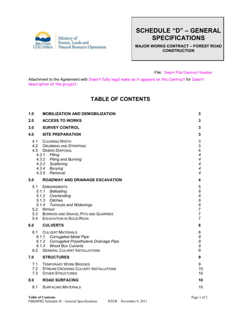
SCHEDULE “D” – GENERAL SPECIFICATIONS MAJOR WORKS CONTRACT – FOREST ROAD CONSTRUCTION File: Insert File/Contract Number Attachment to the Agreement with Insert fully legal name as it appears on the Contract for Insert description of the project. TABLE OF CONTENTS 1.0 MOBILIZATION AND DEMOBILIZATION 3 2.0 ACCESS TO WORKS 3 3.0 SURVEY CONTROL 3 4.0 SITE PREPARATION 3 4.1 CLEARING W IDTH 4.2 GRUBBING AND STRIPPING 4.3 DEBRIS DISPOSAL 4.3.1 Piling 4.3.2 Piling and Burning 4.3.3 Scattering 4.3.4 Burying 4.3.5 Removal 5.0 3 3 4 4 4 4 4 4 ROADWAY AND DRAINAGE EXCAVATION 5.1 EMBANKMENTS 5.1.1 Ballasting 5.1.2 Overlanding 5.1.3 Ditches 5.1.4 Turnouts and Widenings 5.2 RIPRAP 5.3 BORROW AND GRAVEL PITS AND QUARRIES 5.4 EXCAVATION IN SOLID ROCK 6.0 5 6 6 6 6 7 7 7 CULVERTS 8 6.1 CULVERT MATERIALS 6.1.1 Corrugated Metal Pipe 6.1.2 Corrugated Polyethylene Drainage Pipe 6.1.3 Wood Box Culverts 6.2 GENERAL CULVERT INSTALLATIONS 7.0 7.1 7.2 7.3 8.0 8.1 4 8 8 9 9 9 STRUCTURES 9 TEMPORARY W ORK BRIDGES STREAM CROSSING CULVERT INSTALLATIONS OTHER STRUCTURES 9 10 10 ROAD SURFACING 10 SURFACING MATERIALS 10 Table of Contents FS623FRC Schedule D – General Specifications Page 1 of 2 RTEB November 9, 2011 8.1.1 Pit-run Aggregate 8.1.2 Grid-Rolled Aggregate 8.1.3 Screened Aggregate 8.1.4 Crushed Aggregate 8.2 PLACEMENT, PROCESSING AND COMPACTION OF SURFACING MATERIAL 8.3 FINISHED SURFACE 8.4 GRADING 9.0 9.1 9.2 9.3 10.0 10 10 10 10 11 11 11 GRASS SEEDING 11 DRY SEEDING HYDRAULIC SEEDING EROSION CONTROL BLANKETS 11 11 11 CLEANUP 11 LIST OF TABLES Table 1 - Riprap Classes and Sizes Table 2 - Metal Culvert Specifications Table of Contents FS623FRC Schedule D – General Specifications 7 8 Page 2 of 2 RTEB November 9, 2011 GLOSSARY OF TERMS Ballast – Rock or other suitable material placed in the embankment used to improve the stability and load carrying capacity of the roadway. Borrow Pits - A designated area used to obtain material required to form the embankments. Clearing width – The boundary limits of the complete removal and disposal of all standing and fallen trees. Corduroy or Puncheon - Trees or logs placed transversely along the ground surface and covered with suitable subgrade material in order to “float” the road over soft subsoils. Disposal Site – A designated area used to store or dispose of materials from within the clearing width that are not required or suitable for placing in the embankment. Ditch Block - A physical blockage of the ditch line that: (a) is lower than road surface; (b) is located immediately down slope of the cross drain intake; and, (c) prevents large accumulations of water in the ditch by diverting it into the cross drain intake. Drawing(s) - Includes plan profiles, cross sections, mass diagrams, traversed location lines on maps, descriptive literature, illustrations, schedules and any other similar materials provided by the Ministry. Embankment – A structure of soil, aggregate or rock material placed on the prepared ground surface and constructed to complete the road subgrade. End Hauling – The act of moving excess materials as indicated on the road design or Drawings or, where slope stability dictates, to another road section or disposal site. Fly Rock - Rock displaced by blasting and propelled beyond recoverable limits. Forestry License to Cut - An agreement under the Forest Act allowing a person, who occupies Crown land and does not have the right to harvest Crown timber from the land, to cut and/or remove timber on the land. Geosynthetics – Specially fabricated synthetic polymer materials designed with the primary functions of separation, filtration, drainage, aggregate confinement, reinforcement, distribution of load and erosion control. Grubbing and Stripping- The removal and disposal of all organic soils, stumps, downed, buried or nonmerchantable timber, roots, logging slash and other debris from the road prism area. Keying – A bench, trench or structure at the approximate location of the toe of a fill slope constructed to support steep fills. Landing - A leveled area where timber is assembled for transport to the reloading site or conversion facility. L-Line - The designed roadway centre line shown on a Drawing with tangent Point of Intersection (PI), Beginning of Curve (BC), and End of Curve (EC) chainages. Where close control of cut and fill slopes are required, the L-line is established after grubbing and stripping operations by setting grade stakes. Other material (OM) - All excavated material not identifiable as rock Overbreak - Material beyond the proposed or specified limits of excavation which has been excavated, displaced or loosened, usually by blasting. Overlanding - Placing road construction fills directly over organic soil, stumps, and other vegetative materials left in their natural state because of soft ground conditions. P-Line - The preliminary survey line established in the field and plotted on a Drawing to provide the horizontal and vertical control for the roadway centre line. Solid Rock –a concreted mass of materials (rock, dense till, hardpan, partially cemented materials, clay or frozen material) of such density, or so firmly cemented together and are of sufficient hardness to require breaking by continuous drilling and blasting before excavation. It includes stony material occurring in masses, ledges, seams or layers and boulders individually containing a volume of 1.5m³ or more. FS623FRC Schedule D – General Specifications RTEB November 9, 2011 Page 1 of 11 Reference point – an object of more or less permanent character situated outside the clearing width, which is used to relocate a station on the road centerline or other road features by linear and angular measurements. Riparian zone - The land adjacent to the normal high water line in a stream, river, lake, or pond and extending to the portion of land that is influenced by the presence of the adjacent stream, river, lake, or pond. Rippable Rock – is not Solid Rock. It includes those materials that can be loosened using ripping equipment as specified in Schedule C, such as rock, dense till, hardpan, partially cemented materials, clay or frozen material. Riprap – Riprap is hard, durable, angular rock of a quality that will not disintegrate on exposure to water or the atmosphere and meets the specified gradation specifications. Road Prism - The areas containing the roadway and cut and fill slopes. Road Use Permit - The permit issued under the Forest Act giving the permittee the right to use the road subject to terms and conditions. Subgrade - The traveled portion of the road prism upon which additional surfacing material is placed, if required, to provide the running surface. Sub-Excavation – Additional excavation required below the subgrade grade elevations indicated or expected on the Drawings or other specifications. Additional material is paid in accordance with Schedule A. Turnouts - A short auxiliary lane of sufficient width so as to provide for the safe passage of industrial vehicles. Unsuitable Material - Any material that does not meet construction specification requirements for the designed purpose. FS623FRC Schedule D – General Specifications RTEB November 9, 2011 Page 2 of 11 NOTE: ANY REFERENCES TO SCHEDULE C MAY INCLUDE THE DRAWINGS LISTED IN SCHEDULE C AS WELL AS INDIVIDUAL SPECIFICATIONS. 1.0 MOBILIZATION AND DEMOBILIZATION Mobilization and demobilization is defined as: 2.0 (a) the initial transportation of workers, machinery and facilities to the work site; (b) the final removal of workers, machinery and facilities from the work site; and (c) all erection and dismantling activities (e.g., camp set up), until completion of the project. ACCESS TO WORKS The contractor: 3.0 (a) is responsible for the cost of any temporary access works and any damage done to the existing roads or structures as a result of its operations; (b) must ensure that the access to the works is adequate to get the required workers, machinery and facilities to the work site; and, (c) must not block or impede the use of any private access without written consent of the landowner and prior approval of the Ministry Representative. SURVEY CONTROL The P-Line, Reference Points and clearing width boundaries have been marked in the field unless otherwise specified in Schedule C. Reference points and clearing boundaries must be carefully preserved. The Contractor must be satisfied before commencing any work, as to the meaning and correctness of all marks and stakes, as no claim will be entertained for any alleged inaccuracies. Should the Contractor discover or suspect any errors in the marks, the Contractor shall at once discontinue the affected work until such errors are investigated and, if necessary, rectified. The Contractor shall at the Contractor’s own expense provide all other survey control and layout, and shall provide assistance to the Ministry Representative in establishment of lines, grades or controls required for checking or measuring up the work as required. 4.0 SITE PREPARATION 4.1 Clearing Width The Contractor must not operate outside the clearing width without the prior approval of the Ministry Representative except for the purpose of removing dangerous trees or other hazards. The clearing width must be established in accordance with the applicable Forestry Licence to Cut unless otherwise directed by the Ministry Representative. Unless otherwise directed by the Ministry Representative, the Contractor must make a reasonable effort to ensure that all clearing boundary markings are left intact after clearing. Timber must not be placed outside of the clearing width. 4.2 Grubbing and Stripping The Contractor must grub and strip the portion of clearing width area that will be occupied by the road prism. Where the Schedule C so specifies for sections of the road, stumps, roots, embedded logs and other organic debris may be left in place as support material for the road prism. FS623FRC Schedule D – General Specifications RTEB November 9, 2011 Page 3 of 11 Other than trees and stumps with exposed roots or roots which overhang the top of cut, grubbing and stripping is not required between the tops of cuts and adjacent standing timber and the toes of fills and adjacent standing timber. 4.3 Debris Disposal Debris resulting from grubbing and stripping activities, hereafter referred to as “debris” in this section, must not be deposited in areas where the material is capable of damaging forest and other resources. In addition to any other remedial requirements, debris that is deposited in such areas must be immediately removed. Unless otherwise directed by a Ministry Representative, debris must be disposed of in the location(s) and method(s) specified in the Schedule C, including the following applicable specifications: 4.3.1 Piling The Contractor must pile any combustible debris for future burning by other parties. Piles must be constructed in such a manner and of a mix of material that they can be successfully ignited and burned. No soils or non-combustible materials are to be included in the piles. Piles must be located so that there will be no adverse impact on forest and other resources, including standing timber. Piles must also be located such that road operations will not be impacted. 4.3.2 Piling and Burning The Contractor must pile any combustible debris and burn it in accordance with applicable legislation at an appropriate time such that there will be no adverse impact on forest and other resources, including standing timber. Piles must be located such that road operations will not be impacted. Burning is considered to be complete when all combustible materials are reduced to ash, or to a lesser extent as determined by the Ministry Representative. 4.3.3 Scattering Debris must be scattered down slope from the road shoulder and outside of the structural toe of the road prism away from standing timber. Accumulations of debris must be breached at each culvert location to facilitate drainage. Where directed by the Ministry Representative, accumulations of debris must be breached to permit the movement of livestock and wildlife, or for other operational requirements. 4.3.4 Burying All debris must be compacted and placed beyond the edge of the structural fill and away from the edge of standing timber, unless otherwise directed by the Ministry representative. Where trenching is used debris can be placed in the trench or trenches and covered. Debris disposal must replicate existing ground profiles but must not reach within fifty centimetres (50cm) of the road shoulder elevation and must not interfere with any watercourse or natural drainage patterns. Debris must be covered with a minimum of thirty centimetres (30 cm) of soil. Any resulting berms must be breached at each culvert location to facilitate drainage and, where directed by the Ministry Representative, must be breached to permit the movement of livestock and wildlife, or for other operational requirements. 4.3.5 Removal Debris must be transported to a disposal site(s) as specified in the Drawings in Schedule C, or as approved by the Ministry Representative. Disposal sites for debris must be prepared and benched to enable stable placement of the transported debris material. Slopes resulting from transported debris material must be stable at all times. 5.0 ROADWAY AND DRAINAGE EXCAVATION FS623FRC Schedule D – General Specifications RTEB November 9, 2011 Page 4 of 11 Roadway and drainage excavation includes: (a) all excavation other than that related to grubbing and stripping activities in accordance with the following table: Material Types Coarse-Grained Soils Fine-Grained Soils Materials description Road cuts in loose to compact SANDS or SANDS and GRAVELS (not cemented and noncohesive) Road cuts in loose SILTS, or soft cohesive soils such as SILTY CLAYS or CLAYS (not consolidated and not cemented) Dense Glacial Till / Cemented Sands and Gravels Road cuts in dense to very dense GLACIAL TILL (i.e., basal till), or cemented SANDS OR SANDS and GRAVELS Rock Road cuts in strong, good quality ROCK masses with no significant weaknesses Cut Slope Angles Fill Slope Angles 1½ H : 1 V 1½ H : 1 V 1½H : 1V 2H : 1V ¾H : 1V 1½ H : 1 V ¼H : 1V 1H : 1V Note: any variations to these angles would be provided in the Drawings in Schedule C, or as determined by the Ministry Representative. 5.1 (b) the construction of all embankments; (c) excavation of any drainage ditches; (d) the import and placement of material necessary to form a stabilized subgrade in accordance with applicable project specifications; and (e) transporting and disposal of all excess and unsuitable excavated material. Embankments Embankments must be constructed using suitable material and in such a manner as to provide a stable road prism that is compliant with the applicable project specifications described in Schedule C. Embankments must be placed in layers, and hauling and spreading equipment operated uniformly over the full width of each layer, all to compact the materials placed in the embankment. Each embankment layer must be leveled and smoothed before placing subsequent layers. Additional compaction specifications may be described in Schedule C. Layers not to exceed 30 centimetres. All fills must be placed to attain the slope angles specified in this Schedule or in the Drawings listed in Schedule C. Fill slopes determined by the Ministry Representative for the actual soil types encountered in the field take precedence over those shown in this Schedule or on the Drawings listed in Schedule C. Any material utilized as part of the embankment must be competent for fill construction and of optimum quality, sorted to achieve the specified construction requirements, and placed to ensure permanent bonding of the fill material with the original side slopes. Materials that, in the opinion of the Ministry Representative, are unsuitable for the construction of embankments must be removed to disposal sites as directed. Any such unsuitable material subsequently placed in an embankment, FS623FRC Schedule D – General Specifications RTEB November 9, 2011 Page 5 of 11 without the approval of the Ministry Representative, must be removed to disposal sites as directed by the Ministry Representative at the Contractor’s cost. Roads may only be constructed with stumps, roots and embedded logs in the embankment where provided for in the specifications described in Schedule C. Unless the road to be constructed is one that will be constructed of snow and soil combined to form an embankment for use in winter conditions only, frozen material, snow, ice or frozen soils must not be placed in embankments and any such material overlying the surface of a cut, or the site or surface of an embankment must be removed and deposited beyond the edge of the road prism and in accordance with the requirements of the disposal of unsuitable material. For a road that will be constructed of snow and soil combined for use in winter conditions only, refer to Schedule C for specifications. If any geosynthetics are to be utilized in the embankment, refer to Schedule C for specifications. The entire roadway, shoulders, ditches and cut and fill slopes must be neatly trimmed to produce smooth surfaces, slopes and uniform cross-sections in general conformance to the lines, grades and cross-sections shown on the Drawings or in accordance with any specified tolerances described in Schedule C. 5.1.1 Ballasting Ballast must be deposited and spread so that the material is well distributed and the intervening spaces are filled with smaller sizes as may be available to form a stable embankment. When rock ballast is overlain by other materials, the top of the ballast must be sealed with smaller rock particles and suitable soil materials, to prevent the other materials from penetrating into voids in the ballast. To facilitate proper placement and compaction of ballast material, the contractor must carry out ballast treatments in accordance with Schedule C. 5.1.2 Overlanding Where overlanding is specified in the specifications described in Schedule C, or as directed by the Ministry Representative as a result of on-site conditions, road fill must be placed on unstripped organic soil, stumps and vegetative material. Stumps may be inverted so that the root mat of the stump partially supports the fill material. The selection and placement of corduroy/puncheon or geosynthetics must be in accordance with specifications described in Schedule C. 5.1.3 Ditches Ditch construction includes inlets and outlets to culverts, ditch blocks, catch basins and ditching of all kinds to control the transport of water along and from roadways. Sideslopes of a ditch must conform to the constructed embankment slopes and cut slopes. Ditches must be constructed in accordance with the Drawings or the specifications in Schedule C. Where outsloping or insloping the road can replace the need for ditches, such requirements are specified in Schedule C. Except where ditch-water converges at the culvert inlet, ditch blocks must be constructed of impermeable soils extending at least one metre (1.0m) along the ditch immediately downstream of all cross drain culvert inlets. The crest of ditch blocks must be constructed lower than the road shoulder. 5.1.4 Turnouts and Widenings Turnouts and curve widenings must be constructed in accordance with the Drawing, where provided, or in accordance with Schedule C. FS623FRC Schedule D – General Specifications RTEB November 9, 2011 Page 6 of 11 5.2 Riprap The Contractor must protect embankments, dikes, stream banks and channels, culvert inlets and outlets, abutment wings, structural foundations and other specified locations by placing riprap of the type as shown in Table 1 below or in the Drawings listed in Schedule C, at the locations and of the classes specified in Schedule C. Riprap must be placed on firm, stable ground and produce a rock mass of the nominal or required thickness over the area. Any geosynthetic underlay must be provided and placed in accordance with the specifications described in Schedule C. Riprap material must be manipulated as necessary to provide mass stability and a regular surface with a minimum of voids. The gradation of rock sizes in each class of riprap is provided in the table below: Table 1 - Riprap Classes and Sizes Class of Riprap in kilograms (kg) 10 25 50 100 250 500 5.3 Nominal Thickness of Riprap Piece in millimeters (mm) Approximate Rock Gradation: Percentage Larger than Given Rock Mass in kilograms (kg) 350 450 550 700 1000 1200 85% 50% 15% 1.0 2.5 5.0 10 25 50 10 25 50 100 250 500 30 75 150 300 750 1500 Borrow and Gravel Pits and Quarries In cases where the quantity of material taken from the excavation will not be sufficient to form the requisite embankment, the volume deficiency must be supplied by excavating material from within or outside the clearing width or from enlargement of the regular excavations made uniformly on one or both sides of the subgrade. All borrow and gravel pit and rock quarry sites that are not inside the clearing width must be either shown on the Drawings or pre-approved in writing by the Ministry Representative. Borrow and gravel pits and quarries must be grubbed and stripped in accordance with applicable specifications described in Schedule C. Drainage ditches must be constructed to remove all accumulated water from the pit/quarry site, or the pit must be backfilled to prevent the ponding of water. The Contractor must operate the pit or quarry in a manner that will not contaminate remaining granular material and thus limit its future use. The Contractor is responsible for the construction and maintenance of any access roads to pits and quarries. The Contractor must leave any such pits and quarries in a neat and stable condition to the satisfaction of the Ministry Representative. 5.4 Excavation in Solid Rock Excavation materials shall only be considered payable as Solid Rock as provided in Schedule C. The Contractor must remove all overlying materials from areas requiring rock excavation within the clearing width. The Contractor must prepare and excavate all rock to form the subgrade. Rock cuts must be excavated and mucked out fully to twenty centimetres (20 cm) below subgrade elevation. The Contractor is responsible for the rock excavation methods used and for any damage to the rock structure or road prism resulting from direct application of the techniques used. FS623FRC Schedule D – General Specifications RTEB November 9, 2011 Page 7 of 11 Where the excavation method is drilling and blasting, the Contractor must provide the blasting log and other relevant information regarding any blast upon request of the Ministry Representative. All drilling and blasting must be done in a manner that: (a) retains all blasted rock within the cleared width. (b) provides a stable back slope; (c) does not destabilize the fill slope; (d) minimizes the amount of rock loss; and (e) minimizes overbreak. Developed rock must produce a profile of material that can be fully utilized, in accordance with the specifications described in Schedule C. Rock that does not conform to the profile must be removed and disposed of at a suitable disposal site. Unless the rock can be utilized as embankment material that would otherwise have to be borrowed, all overbreak must be removed and disposed of at a suitable disposal site at the Contractor’s cost. The Contractor must remove all dangerous, loose and overhanging rock. 6.0 CULVERTS The types of culverts that are to be used on this project are specified in Schedule C. 6.1 Culvert Materials 6.1.1 Corrugated Metal Pipe Culverts and coupler systems must be of galvanized, corrugated metal pipe in accordance with the current version of Canadian Standards Association C.S.A.- Can 3-G401. All couplers must be double wide (600mm) and installed according to the manufacturer’s specifications. Minimum pipe specifications are as follows: Table 2 - Metal Culvert Specifications Pipe Diameter in Minimum Pipe Corrugation millimeters (mm) Thickness dimensions in for Metal Pipe-Sectional millimeters (mm) in millimeters (mm) 400 - 600 1.6 68 x 13 600 Coast 2.0 68 x 13 800 - 1000 2.0 68 x 13 1400 2.0 125 x 25 1200 - 1400 2.8 68 x 13 1600 2.0 125 x 25 1600 - 1800 3.5 68 x 13 The minimum length of any pipe section in a coupled culvert is 3.0 metres. FS623FRC Schedule D – General Specifications RTEB November 9, 2011 Page 8 of 11 6.1.2 Corrugated Polyethylene Drainage Pipe Corrugated polyethylene (PE) and Poly vinyl chloride (PVC) or ribbed PVC drainage pipe, fittings and couplers must be manufactured from plastic in accordance with current version of CSA Standard B182 and meet current CSA standards for impact strength, pipe stiffness and flattening. PE pipe stiffness shall meet or exceed 210 Kilopascals (kPa). PVC pipe stiffness shall meet or exceed 260 Kilopascals (kPa). All plastic pipe must be double walled for the entire length under the embankment fill. The minimum length of any pipe section in a coupled culvert is 3.0 metres. 6.1.3 Wood Box Culverts Material and dimensions for the construction of wood box culverts must be approved by the Ministry Representative. Logs may be obtained from the clearing width or from areas approved by the Ministry Representative. Wood box culvert construction must conform to the requirements for design and construction of log culverts in the Forest Road Engineering Guidebook. 6.2 General Culvert Installations Culverts must be installed at locations described in Schedule C, or as directed by the Ministry Representative to suit actual site conditions. Culverts must be constructed concurrently with subgrade construction. Culvert lengths must conform to the specifications described in Schedule C, or where not specified, must project between fifty and seventy centimetres (50 - 70 cm) beyond the face of the embankment. The Contractor must excavate a trench for a pipe culvert to a width of not less than twice the culvert diameter. The grade of the trench must replicate natural slope conditions unless otherwise provided in the specifications described in Schedule C, but for cross drains the trench must have a minimum grade of 0.5 percent to facilitate natural drainage. The culvert bed may require a camber where necessary to maintain positive drainage through the pipe. The camber will be as required by the Ministry Representative. Cross-drain culverts must be skewed to the perpendicular of the road centre line, by 3 degrees for each 1 percent that the road grade exceeds 3 percent, to a maximum of 45 degrees, unless otherwise directed by the Ministry Representative. Trenches must be backfilled evenly in lifts not exceeding twenty centimetres (20 cm) on each side of the culvert. Backfill materials must not contain any frozen material, snow, ice or organic matter. Backfill material having a maximum piece size of fifteen centimetres (15 cm) in diameter must be placed over all culverts for the full width of the trench to a minimum depth of thirty centimetres (30 cm) or a depth of one-half the diameter of the culvert, whichever is greater. Any backfill, or any portion thereof, that has suffered reduction in density after compacting due to frost action, rain or for any other reason, must be re-compacted or removed and replaced by the Contractor before any material is placed for the succeeding lift. Where inlet and outlet protection is required, the materials and placement must conform to the specifications described in Schedule C. When water from culvert outlets is to be directed onto fill slopes, riprap or other approved protective measures must be installed to dissipate water energy. 7.0 STRUCTURES 7.1 Temporary Work Bridges The Contractor is responsible for the installation and subsequent removal of any temporary work bridges required for access during construction, and all costs for such bridges are borne by the Contractor. FS623FRC Schedule D – General Specifications RTEB November 9, 2011 Page 9 of 11 The stream banks must not be disturbed and damage to ground cover and riparian vegetation must be minimized. Work bridges must be removed at the end of construction and during any periods of high water that may otherwise adversely impact the structure. 7.2 Stream Crossing Culvert Installations During culvert placement, unless otherwise approved by the Ministry Representative, the Contractor must use an appropriate method of isolating the work site from the stream, such as the diversion of the stream around the culvert site, and place the culvert in the ‘dry’. Such diversions must be carefully executed to ensure that siltation is kept to a minimum and the stream controlled at all times. All materials and placement must conform to the drawing, or as described in specifications in Schedule C. Fish stream crossings must be constructed in accordance with any in-stream work windows, stream protection, fish salvage, erosion and sediment control measures described in Schedule C. Restrict all work within the high water, wetted perimeter to the absolute minimum necessary to construct the works. 7.3 Other Structures Refer to specifications described in Schedule C. 8.0 ROAD SURFACING Road surfacing consists of supplying, hauling and placing of aggregate base or surface course on the subgrade or base in accordance with the Drawings or as specified in Schedule C. 8.1 Surfacing Materials Aggregates that are to be used as surfacing materials must be free from organic matter or other deleterious material and must conform with the following specifications in addition to applicable specifications described in Schedule C: 8.1.1 Pit-run Aggregate Pit-run aggregates must consist of native or blasted material of a size and grading that can be taken directly from the source and placed on the road without crushing or screening. Work may include the addition of fines to bind the surfacing materials together. The maximum size of placed pit run material to be used as surfacing must be as specified in Schedule C. Materials must be obtained from sources or stockpiles specified in Schedule C or as approved by the Ministry Representative. 8.1.2 Grid-Rolled Aggregate Grid-rolled aggregate must consist of native materials of a quality that can be taken directly from the source, without crushing or screening, and broken down on the road by grid-rolling. No gradation is required, other than maximum size as specified in Schedule C. 8.1.3 Screened Aggregate Material must consist of gravel, talus rock, sand, shale, or other suitable material, and be hard and durable, such that a hand held specimen requires many blows of the hammer end of a geological pick to fracture it. The gradation requirements must be as specified in Schedule C. 8.1.4 Crushed Aggregate Aggregate for crushed base or surface courses must be crushed stone, or gravel meeting the gradation requirements as specified in Schedule C. The Contractor must sample, inspect and test the materials to substantiate that all crushed material meets the gradation requirement. Testing requirements must be carried out in accordance with Schedule C. Test results must be provided to the Ministry Representative. FS623FRC Schedule D – General Specifications RTEB November 9, 2011 Page 10 of 11 8.2 Placement, Processing and Compaction of Surfacing Material The source and type of surfacing material must be approved by the Ministry Representative before being applied to the road subgrade. Surfacing material must be placed on the subgrade, in layers of sufficient thickness to allow consistent compaction throughout the layer, spread and shaped in general conformance with the required depths as shown on the Drawings or in Schedule C. The width of surfacing material must be sufficient to stabilize the road subgrade width, including turnouts. In accordance with the requirements of Schedule C, filler or binder must be uniformly blended with surfacing material on the road. Filler or binder material must be free from stones, vegetative matter and other deleterious materials. If surfacing materials do not contain the correct moisture content to permit proper compaction, the Contractor must add or remove moisture as required. Suitable compaction is obtained when the road achieves the requirements in Schedule C. 8.3 Finished Surface In accordance with Schedule C, after placing the surfacing material, the entire roadway, shoulders and ditches must be neatly trimmed in general conformance with the dimensions as shown on the Drawings or on the Typical Roadway Cross Section in Schedule C. Works shall include crowning and compacting of the finished road surface to ensure that water drainage is commensurate with the potential for erosion of the surfacing material. 8.4 Grading Where the finished road surfacing material is comprised of a granular material that can be effectively shaped by a motor grader, final shaping of the road and ditch will be to the final trim, level, and grade of the road and ditch Sufficient effort requiring multiple passes may be required to sort materials to provide for the best possible finish of the road surface as described in “Finished Surface”, Clause 8.3. Grading must be completed during optimum weather conditions. 9.0 GRASS SEEDING The Contractor must supply and apply an erosion control seed mix, using application method (s) and mix designs as specified in Schedule C, on all exposed mineral and organic soils that are subject to surface erosion within the clearing width excluding the road surface. 9.1 Dry Seeding The Contractor must distribute dry seed uniformly over the surface area. 9.2 Hydraulic Seeding The Contractor must thoroughly mix seed, fertilizer and hydraulic mulch in water slurry and distribute uniformly over the surface. The Contractor must take suitable precautions to prevent fertilizer in solution from coming in contact with foliage of any trees or susceptible vegetation. The Contractor must promptly rectify any overspray or damage that occurs at the Contractor’s cost. 9.3 Erosion Control Blankets The Contractor must supply, apply and anchor erosion control blankets over designated areas in accordance with the manufacturer’s instructions, unless otherwise specified in Schedule C. 10.0 CLEANUP At the conclusion of the works, the Contractor must remove the Contractor’s surplus products, tools, construction machinery and equipment not required for the performance of the remaining work. The Contractor must also remove waste products and debris other than that caused by the Ministry, other Contractors or their employees, and leave the work site clean and suitable for occupancy or use by the Ministry, unless otherwise specified. FS623FRC Schedule D – General Specifications RTEB November 9, 2011 Page 11 of 11
