POLA_24545_sm_suppinfo
advertisement
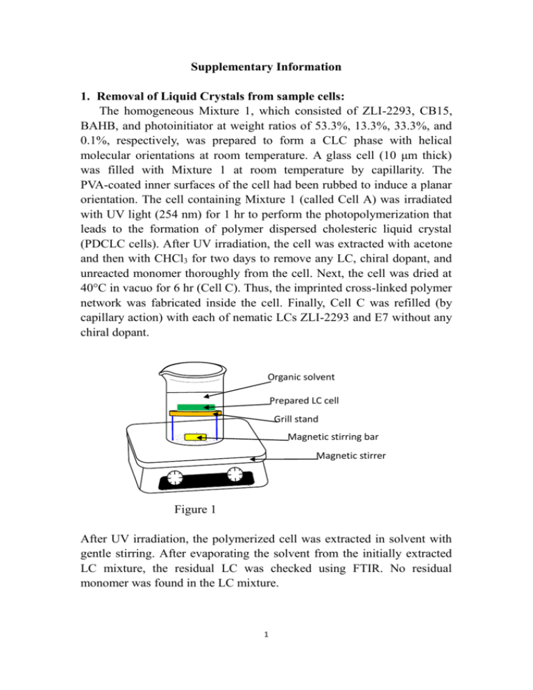
Supplementary Information 1. Removal of Liquid Crystals from sample cells: The homogeneous Mixture 1, which consisted of ZLI-2293, CB15, BAHB, and photoinitiator at weight ratios of 53.3%, 13.3%, 33.3%, and 0.1%, respectively, was prepared to form a CLC phase with helical molecular orientations at room temperature. A glass cell (10 μm thick) was filled with Mixture 1 at room temperature by capillarity. The PVA-coated inner surfaces of the cell had been rubbed to induce a planar orientation. The cell containing Mixture 1 (called Cell A) was irradiated with UV light (254 nm) for 1 hr to perform the photopolymerization that leads to the formation of polymer dispersed cholesteric liquid crystal (PDCLC cells). After UV irradiation, the cell was extracted with acetone and then with CHCl3 for two days to remove any LC, chiral dopant, and unreacted monomer thoroughly from the cell. Next, the cell was dried at 40°C in vacuo for 6 hr (Cell C). Thus, the imprinted cross-linked polymer network was fabricated inside the cell. Finally, Cell C was refilled (by capillary action) with each of nematic LCs ZLI-2293 and E7 without any chiral dopant. Organic solvent Prepared LC cell Grill stand Magnetic stirring bar Magnetic stirrer Figure 1 After UV irradiation, the polymerized cell was extracted in solvent with gentle stirring. After evaporating the solvent from the initially extracted LC mixture, the residual LC was checked using FTIR. No residual monomer was found in the LC mixture. 1 2. Fabrication of sample cells: Spacer (Side view) (Top view) Figure 2 A glass cell (20 μm thick) was filled, by capillarity, with Mixture 1 at room temperature. The PVA-coated inner surfaces of the cell had been rubbed to induce a planar orientation. 3. Photo-Polymerization: UV lamp (254 nm, 6 Watt) 3 cm Sample cell Figure 3 Photo-polymerization was carried out using a 254 nm UV-lamp for 1 hour. The distance between UV-lamp and sample cell is 3 cm. 4. Measurement of reflection spectra: Optical fiber (Ocean Optics R400-7-SR) Light source (Ocean Optics LS-1) Detector Sample cell Data processor and Recorder Figure 4 An optical fiber system was used to measure the reflection spectrum of the sample cells. Stander plates were used for both zero and complete reflection calibrations. After polymerization, the cross-linked polymer matrix could not be further dissolved in liquid crystals. Consequently, the imprinted helical 2 pitch was considered to be fixed. The pitch of cholesteric liquid crystals was estimated using Equation (1). Theoretically, from UV-vis spectra (λ0), the approximate pitch of cholesteric liquid crystals can be calculated. λ0 = navg P (1) 5. Molecular structure of difunctional photopolymerizable monomer BAHB, 4,4’-Bis(6-acryloyxy-hexyloxy)biphenyl, which was synthesized in our lab. The detailed process has been previously described in the following article. Title: Fabrication and characterization of polymer stabilized cholesteric liquid crystal cells with chiral monomers derived from borneol Authors: Liu, Jui-Hsiang; Hung, Hsien-Jung Source: Liquid Crystals, Volume 32, Number 1, January 2005 , pp. 133-142(10) (C30H38O6) 3
