3 Procedure: wheel and axle
advertisement
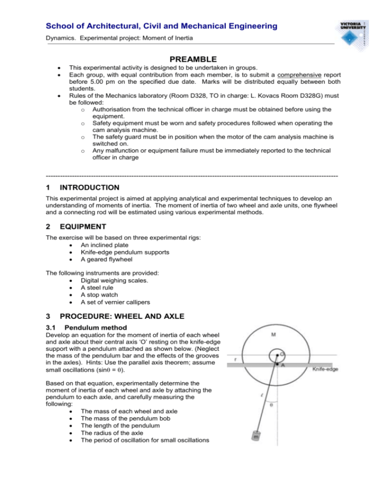
School of Architectural, Civil and Mechanical Engineering Dynamics. Experimental project: Moment of Inertia PREAMBLE This experimental activity is designed to be undertaken in groups. Each group, with equal contribution from each member, is to submit a comprehensive report before 5.00 pm on the specified due date. Marks will be distributed equally between both students. Rules of the Mechanics laboratory (Room D328, TO in charge: L. Kovacs Room D328G) must be followed: o Authorisation from the technical officer in charge must be obtained before using the equipment. o Safety equipment must be worn and safety procedures followed when operating the cam analysis machine. o The safety guard must be in position when the motor of the cam analysis machine is switched on. o Any malfunction or equipment failure must be immediately reported to the technical officer in charge --------------------------------------------------------------------------------------------------------------------------- 1 INTRODUCTION This experimental project is aimed at applying analytical and experimental techniques to develop an understanding of moments of inertia. The moment of inertia of two wheel and axle units, one flywheel and a connecting rod will be estimated using various experimental methods. 2 EQUIPMENT The exercise will be based on three experimental rigs: An inclined plate Knife-edge pendulum supports A geared flywheel The following instruments are provided: Digital weighing scales. A steel rule A stop watch A set of vernier callipers 3 3.1 PROCEDURE: WHEEL AND AXLE Pendulum method Develop an equation for the moment of inertia of each wheel and axle about their central axis ‘O’ resting on the knife-edge support with a pendulum attached as shown below. (Neglect the mass of the pendulum bar and the effects of the grooves in the axles). Hints: Use the parallel axis theorem; assume small oscillations (sin = ). Based on that equation, experimentally determine the moment of inertia of each wheel and axle by attaching the pendulum to each axle, and carefully measuring the following: The mass of each wheel and axle The mass of the pendulum bob The length of the pendulum The radius of the axle The period of oscillation for small oscillations School of Architectural, Civil and Mechanical Engineering Dynamics. Experimental project: Moment of Inertia 3.2 Inclined plane method Using the work-energy method, develop an equation for the moment of inertia of each wheel and axle about their central axis when rolling between two points down an inclined plane. Hints: Ignore frictional losses; the only force acting on the system is gravity (constant acceleration). Based on that equation, experimentally determine the moment of inertia of each wheel and axle by allowing each axle to roll down the inclined plane and carefully measuring the following: The rolling distance travelled The vertical distance travelled The mass of each wheel and axle The average time of travel 3.3 The geometrical calculation method Estimate the moment of inertia of each wheel and axle about their central axis by carefully measuring the mass and dimensions of each wheel and axle. 4 4.1 PROCEDURE: FLYWHEEL Falling weight method Measure the flywheel diameter. Measure the mass of the bob. Wrap the cotton string around the flywheel rim and attach the bob. Adjust the string length so that it automatically detaches from the flywheel rim as the bob touches the ground. Estimate the falling distance of the bob by turning the flywheel backward. Release the flywheel and record the time taken for the mass to reach the ground Record the total number of revolutions undergone by the flywheel between the time the bob hit the ground and the flywheel came to a complete stop. Using the work-energy method, develop an equation for the moment of inertia of the flywheel about its central axis as a function of time of travel (bob) and number of flywheel rotations during deceleration. Ignore any frictional losses. Hint: This is a constant acceleration situation. 5 5.1 PROCEDURE: CONNECTING ROD Compound pendulum method Measure the mass of the connecting rod Suspend the rod by one end on the knife edge and record the average period of oscillations for small oscillations Suspend the rod by the other end on the knife edge and record the average period of oscillations for small oscillations Measure the distance between the two support points. Develop an equation for the moment of inertia of the connecting rod about its centre of mass as a function of the periods of oscillation measured. Hints: for small oscillations (sin = ); use the parallel axis theorem.


