THIN LENSES: APPLICATIONS
advertisement
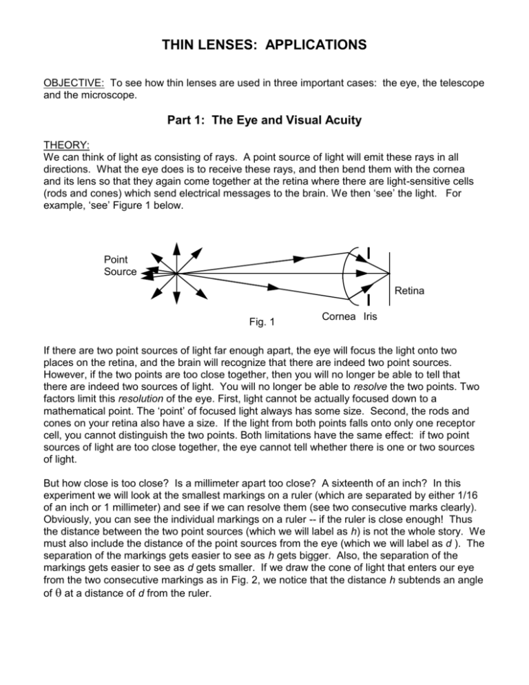
THIN LENSES: APPLICATIONS OBJECTIVE: To see how thin lenses are used in three important cases: the eye, the telescope and the microscope. Part 1: The Eye and Visual Acuity THEORY: We can think of light as consisting of rays. A point source of light will emit these rays in all directions. What the eye does is to receive these rays, and then bend them with the cornea and its lens so that they again come together at the retina where there are light-sensitive cells (rods and cones) which send electrical messages to the brain. We then ‘see’ the light. For example, ‘see’ Figure 1 below. Point Source Retina Fig. 1 Cornea Iris If there are two point sources of light far enough apart, the eye will focus the light onto two places on the retina, and the brain will recognize that there are indeed two point sources. However, if the two points are too close together, then you will no longer be able to tell that there are indeed two sources of light. You will no longer be able to resolve the two points. Two factors limit this resolution of the eye. First, light cannot be actually focused down to a mathematical point. The ‘point’ of focused light always has some size. Second, the rods and cones on your retina also have a size. If the light from both points falls onto only one receptor cell, you cannot distinguish the two points. Both limitations have the same effect: if two point sources of light are too close together, the eye cannot tell whether there is one or two sources of light. But how close is too close? Is a millimeter apart too close? A sixteenth of an inch? In this experiment we will look at the smallest markings on a ruler (which are separated by either 1/16 of an inch or 1 millimeter) and see if we can resolve them (see two consecutive marks clearly). Obviously, you can see the individual markings on a ruler -- if the ruler is close enough! Thus the distance between the two point sources (which we will label as h) is not the whole story. We must also include the distance of the point sources from the eye (which we will label as d ). The separation of the markings gets easier to see as h gets bigger. Also, the separation of the markings gets easier to see as d gets smaller. If we draw the cone of light that enters our eye from the two consecutive markings as in Fig. 2, we notice that the distance h subtends an angle of at a distance of d from the ruler. Thin Lenses: Applications 2 d h Eye Fig. 2 As d increases, the angle decreases. At the distance where the markings start to become unresolvable, we say that we have reached the resolution angle of the eye (eye). Referring to Fig. 2, this angle is given by tan(/2) = (h /2) / d. Because this angle is very small, we can make the ‘small angle approximation’ [tan(/2) ~ /2 (radians)] and write that eye (rads) = h / d (1) This is equivalent to saying that the distance h is approximately the arc length swept out by d if is small. PROCEDURE: 1. Decide whether you will work with the sixteenth-of-an-inch markings or the millimeter markings of the ruler and record the appropriate value for h (1/16 inch or 1 mm). Have your partner hold up the ruler. Slowly walk away from the ruler until you can no longer distinguish one marking from the next marking. Measure the distance (d ) between your eyes and the ruler. (If you have glasses or can easily remove your contacts, you may wish to perform this experiment with and without your glasses or contacts.) REPORT: 1. Use Eq. (1) to calculate the resolution angle of your eye in radians. Convert this angle to degrees. Since it is such a small angle, it is more convenient to express it in minutes of arc or seconds of arc. Convert the angle to arcminutes and then to arcseconds. CONVERSIONS: There are 180 degrees in radians (180º = rads). There are 60 arcminutes in one degree (just like 60 minutes in one hour). There are 60 arcseconds in one arcminute (just like 60 seconds in one minute). Part 2: The Telescope THEORY: A refracting telescope is a combination of two positive lenses used to view distant objects. The first lens (the objective) is used to form an image at a distance of approximately one focal length away from the lens. The second lens (the eyepiece) is used as a magnifying glass to enlarge and examine this image. PROCEDURE: 1. Use the ‘hall method’ that you learned from the Thin Lens experiment to determine the approximate focal lengths of each of your two lenses. (The focal lengths should be different.) Also note which of the two lenses gives the bigger image, and which lens is the "stronger" lens (i.e., the better magnifying glass). Thin Lenses: Applications 3 2. To make a telescope, we will use one lens to provide an image and use the other lens as a magnifying glass. Therefore we will use the lens that gave the bigger image as the objective lens and the lens that is a better magnifying glass as the eyepiece. The distance between the two lenses should be approximately equal to the sum of the two focal lengths. Look at something far away using this telescope by placing your eye near the eyepiece and looking through it so that you also then look through the objective lens. You may have to change the distance between the lenses slightly to obtain the best focus. (This part is hard to do. With a little patience you should see that this combination of lenses does indeed act like a telescope.) 3. After you have successfully completed Step 2, look through your telescope at the ruler with the markings as in the first part of the experiment. You may have to slightly change the distance between lenses to focus the telescope as the ruler is placed at different positions. How far away can you now place the ruler and still resolve the individual markings? Measure this distance d, which for a telescope is the distance from the object to the objective lens. REPORT: 1. Record the focal lengths of the lenses. Indicate which of the two lenses gave the biggest image in the hall, and which acted as the best magnifying glass. 2. Using your measured value of d, calculate the resolution angle of the telescope (tel) using Eq. (1). Again express the angle in radians, degrees, arcminutes, and arcseconds. 3. The useful magnification of a telescope can be found by dividing the resolution angle of the eye by the resolution angle of the telescope, Museful = eye / tel Calculate the useful magnification of your telescope. [NOTE: The distance to resolve the markings with the telescope should be greater than the distance with just the eye, and so eye should be greater than tel.] 4. The theoretical magnification of a telescope is usually given as the ratio of the focal length of the objective (the bigger focal length) to the focal length of the eyepiece (the smaller focal length), Mtheory = fobj / feye Calculate and record this theoretical magnification. 5. Compare the two magnifications, and discuss why they are different. 6. Why did you have to move the position of the lenses to focus the telescope? Thin Lenses: Applications 4 Part 3: The Microscope THEORY: The microscope works with two positive lenses to magnify something that is small but close. The final image is in fact bigger than the object, and the final image is located at the ‘easy viewing’ distance of ~25 cm from the eye (and hence from the eyepiece lens). [The telescope also works with two positive lenses to magnify something, but in this case the object is far away and the telescope actually only magnifies the angle that the image makes with the eye. Another way of saying this is that it makes the object seem closer than it actually is.] In a microscope, the lens close to the object (the objective), is used as a projector: it projects a real image that is bigger than the object, and the object distance is small in comparison with the image distance, with both distances being positive. [You did this with a positive lens in the Thin Lenses: Basics experiment.] The second lens (the eyepiece) is used as a magnifying lens. It takes as its object the image of the objective lens. However, instead of projecting a real image on the other side of the lens, the eyepiece lens creates a virtual image on the same side of the lens as its object. Most microscopes are designed so that this virtual image is seen at the easy viewing distance of 25 cm from the eyepiece. Hence, we need s’e to be -25 cm. [The eye then uses this virtual image as its object and acts as a camera to record an image on the retina of the eye.] PROCEDURE: 1. The object for our microscope will be the same object we used previously. The small tick marks are 1 mm apart. Place the object at one end of the rail. Leave the lamp off. 2. In our microscope, we want to have a magnifying power of 2 for the objective lens: Mo = -s'o / so = -2 (1) We will use an objective lens with a focal length of approximately +10 cm. Recall that 1/fo = 1/so + 1/s'o (2) From these two equations, calculate the necessary so and s'o values. 3. Using the so value found in Step 2, position the objective lens a distance so from the object. 4. We now will use another lens of approximately +10 cm focal length for the eyepiece. In this case we know fe = +10 cm, and we want s'e = -25 cm. Thus, calculate the necessary se using the thin lens equation (1/fe = 1/se + 1/s'e ). Then calculate the magnification of the eyepiece (Me = -s'e/se ). 5. Now position the eyepiece a distance s'o + se from the objective lens. 6. Look through the eyepiece so that you also look through the objective lens. You should see the tick marks magnified by a total power of Mtot = Mo x Me . You may have to adjust the focus by moving the object slightly (due to the lenses not having exactly 10 cm focal length). Verify that these two lenses do indeed act as a microscope, and then calculate the theoretical total magnification of this microscope. Note that as you adjust the distance your eye is from the eyepiece you also adjust how much of the objective lens you can successfully look through. There should be a best eye to eyepiece distance to get the largest field of view. Thin Lenses: Applications 5 7. To show that the objective lens does indeed create a real image and that this real image is roughly Mo bigger than the object, place a ruler between the eyepiece and objective lens at a position approximately se from the eyepiece. You should see that both the ruler and the tick marks are in focus. Now compare the spacing of the tick marks with the spacing of the millimeter markings of the ruler. What does the tick mark spacing seem to be as measured by the ruler? Is the spacing in fact Mo bigger than it really is on the object? (2 x 1 mm = 2 mm)? 8. To measure the size of a virtual image is hard because the light does not really come from that place. Thus we will not try to verify the exact value of Me. We can, however, observe that the eyepiece does indeed magnify the tick marks just as it magnifies the millimeter markings of the ruler. 9. Note whether the image of the object is inverted. Now note whether the eyepiece inverts the image of the ruler. From this, what do you conclude about whether the objective lens inverts the image? Is this consistent with how a projector lens works? 10. REPEAT Steps 2-10 but adjust the lenses so that the microscope objective gives a magnification of -5 instead of -2. REPORT: 1. Draw a diagram of the first microscope setup. On the diagram indicate the object, the objective lens, the eyepiece lens. Also indicate the following distances: so, s'o, se, and s'e. ------------------For both microscopes: 2. Show your calculations for so, s’o and se. 3. Show your calculations for Mo, Me, and Mtot. 4. Show your calculation to verify Mo from Step 7. 5. Record your observations and discuss the questions in Step 9. --------------------6. When you look into some microscopes, you can see a set of cross-hairs or a ruled scale to measure sizes of features on your specimen (such a scale is called a reticule). Where are the actual cross-hairs or reticule placed in a microscope? (Contemplate Step 7!) 7. Comment on the differences in the fields of view and the difficulties of focusing using the microscope with the higher magnification.

