High energy optics handout
advertisement
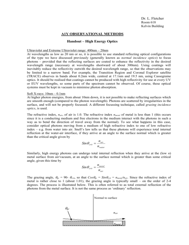
Dr. L. Fletcher Room 618 Kelvin Building A1Y OBSERVATIONAL METHODS Handout – High Energy Optics Ultraviolet and Extreme Ultraviolet range: 400nm – 20nm At wavelengths as low as 20 nm or so, it is possible to use standard reflecting optical configurations of the type we have discussed previously (generally known as normal incidence optics) to focus photons – provided that the reflecting surfaces are coated to enhance the reflectivity in the desired wavelength range (necessary at wavelengths shortward of about 300nm). Using coatings will inevitably reduce the reflectivity outwith the desired wavelength range, so that the observations may be limited to a narrow band. For example, the Transition Region and Coronal Explorer satellite (TRACE) observes in bands about 0.2nm wide, centred at 17.1nm and 19.5 nm, using Cassegraine optics. It should be realised that coatings cannot be produced with high reflectivity for use at every UV or EUV wavelengths, so some parts of the spectrum cannot be observed. Of course, these optical systems must be kept in vacuum to minimise photon absorption. Soft X-rays: 10nm – 0.1nm At higher photon energies, from about 10nm down, it is not possible to make reflecting surfaces which are smooth enough (compared to the photon wavelength). Photons are scattered by irregularities in the surface, and will not be properly focussed. A different focussing technique, called grazing incidence optics, is used. The refractive index, nair, of air is 1.0. The refractive index nmetal of metal is less than 1 (this occurs since it is a conducting medium and free electrons in the medium interact with the photons in such a way as to bend the direction of travel away from the normal). To see what happens in this case, consider optical photons moving from a medium of high refractive index to one of low refractive index – e.g. from water into air. Snell’s law tells us that these photons will experience total internal reflection at the water-air interface, if they arrive at an angle to the surface normal which is greater than the critical angle given by Sin crit nair nwater Similarly, high energy photons can undergo total internal reflection when they arrive at the (low n) metal surface from air/vacuum, at an angle to the surface normal which is greater than some critical angle, given this time by Sin crit nmetal nair The grazing angle, gr = 90- crit, so that Cosgr = Sincrit = nmetal/nair. Since the refractive index of metal is rather close to 1 (about 1.01), the grazing angle is typically small – on the order of 2-4 degrees. The process is illustrated below. This is often referred to as total external reflection of the photons from the metal surface. It is not the same process as ‘ordinary’ reflection. Normal to surface gr nair nmetal This process can be used to direct photons, and therefore to focus them, which is done using metal surfaces having the form of a parabola or hyperbola of revolution (i.e. the surface described when a parabola or hyperbola is rotated about an axis). This is how X-ray telescopes are made. Cross sections through two configurations, the Wolter I and Wolter II configurations, are shown below. Since light has to be prevented from passing ‘straight through’ the telescope, a baffle is put in the middle (used as a reflecting surface in the Wolter II configuration, lower sketch). This means that the effective area of the telescope is much smaller than its actual area. To increase the effective area, nested paraboloids are sometimes used (Kirkpatrick-Baez design, not shown, but used for example in the Chandra X-ray telescope.) Collimating Optics for Hard X-rays (0.1nm- 0.001nm, or ~10 to 1000 keV) At very high energies, the use of grazing incidence optics is also not possible – the grazing angle becomes very small and the focal length impractically long. Collimating optics are then used. Collimating optics does not involved focussing photons, rather photons are blocked or transmitted to a detector, depending on the angle at which they arrive at the telescope. Angular information can then be deduced. Photon not transmitted Photon transmitted d h tr detector Collimating optics are made by constructing arrays of metal slats which are opaque to photons, and separated by small distances. Typical slat thicknesses and separations are 20 – 40 microns (comparable to a human hair): measurements and manufacture have to be very precise! In the above figure, a photon arriving at a small angle would be transmitted by the slats, and reach the detector at the base, whereas one arriving at an angle larger than some critical transmission angle, tr, would not. The value of tr is given by geometry: Tantr d , h where d is the slat spacing and h is the height of the slats. By using a number of grids with different ratios d/h, one can observe photons from a range of different angles – i.e. different positions on the sky. By mounting the grids in different orientations, or so that they spin (for example as is done on the Ramaty High Energy Solar Spectroscopic Imager Satellite), a two-dimensional picture of the source on the sky can be built up. It should be noted here that the process of working out what the source looks like armed only with this rather convoluted and ambiguous angular information is not straightforward, involving advanced mathematics. Nevertheless, it can be done, and is used for imaging high-energy astrophysical sources, including the Sun.

