Proj Assgn A - FPA Verification
advertisement
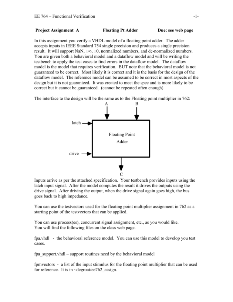
EE 764 – Functional Verification Project Assignment A -1Floating Pt Adder Due: see web page In this assignment you verify a VHDL model of a floating point adder. The adder accepts inputs in IEEE Standard 754 single precision and produces a single precision result. It will support NaN, ±∞, ±0, normalized numbers, and de-normalized numbers. You are given both a behavioral model and a dataflow model and will be writing the testbench to apply the test cases to find errors in the dataflow model. The dataflow model is the model that requires verification. BUT note that the behavioral model is not guaranteed to be correct. Most likely it is correct and it is the basis for the design of the dataflow model. The reference model can be assumed to be correct in most aspects of the design but it is not guaranteed. It was created to meet the spec and is more likely to be correct but it cannot be guaranteed. (cannot be repeated often enough) The interface to the design will be the same as to the Floating point multiplier in 762: A B latch Floating Point Adder drive C Inputs arrive as per the attached specification. Your testbench provides inputs using the latch input signal. After the model computes the result it drives the outputs using the drive signal. After driving the output, when the drive signal again goes high, the bus goes back to high impedance. You can use the testvectors used for the floating point multiplier assignment in 762 as a starting point of the testvectors that can be applied. You can use process(es), concurrent signal assignment, etc., as you would like. You will find the following files on the class web page. fpa.vhdl - the behavioral reference model. You can use this model to develop you test cases. fpa_support.vhdl – support routines need by the behavioral model fpmvectors - a list of the input stimulus for the floating point multiplier that can be used for reference. It is in ~degroat/ee762_assign. EE 764 – Functional Verification -2- fpa_df_v3.vhdl – the dataflow model that needs to be verified Other NOTES for floating point adder. _______________________________________________ You will work in groups of four for this assignment. Documents Due: (Check course web page for due date) 1. A Verification Plan – The plan for verification of this unit. Turn in a test plan that details the test methodology to be employed and the test to be applied to the model. Details how the test vectors are going to be generated. Explain why these are the test vectors and the coverage of the design that is expected. Note that this is a transaction based verification effort. Each transaction consists of the input stimulus and the expected result. It is possible to improve the verification effort in debugging where the error occurred by also including in each transaction the value at intermediate points in the design. This is possible as this is a white box verification effort. 2. A Verification Report A report that detail the accomplishment of the Verification Plan. It will have appropriate listings showing the results of simulation and how the results were checked. How the results are to be checked should have been explained in the test plan. Part of this report is an appendix that has: A copy of the VHDL code of the testbench. A copy of all the test vectors and their expected result. The code used to generate the test vectors. A zoom->full_size waveform and a waveform of a appropriate cycles where the data can be seen on the bus. If there are errors, information that can be used to diagnose the bug. EE 764 – Functional Verification -3- EE 764 – Functional Verification Project Assignment A-1 -4Floating Pt Adder DUE: Mon Apr 19 This is a minor extension to the first project. We will use the coverage feature of the Model Sim Simulator to examine the effectiveness of our tests. Procedure: 1. start up the simulator using the command vsim -coverage 2. Load your fpa test bench for simulation as you did for the assignment 3. Under the view menu go to the coverage selection and turn on (chk marked) all but the Current Exclusions selection. Note the changes to the windows. 4. In the Workspace window expand out the + on the test bench and select the fpa entity/architecture. This will match the label you used on your instantiation of the unit. Note that the code in the Missed Coverage window changes. 5. Double click on the instance listed in the Instance Coverage window to bring up the source window. 6. Now run the simulation for 100 ns. Record any statements listed in the missed coverage window for you report. 7. In the source window make sure that Show Coverage Numbers is on. (on View menu) 8. How many times is statement 178: underflow <= exp_val_adj(8); executed? 9. Does coverage tell you anything about your tests? And the unit under test? Submit a report on your exploration of the use of coverage. You may also want to view the Help pages for Model Sim. Options on the vsim command that may help in verification: -assertfile filename creates a file where all message from assertions are stored -coverage the point of this assignment Print a coverage report (see help menu for information on this) that details the branch, condition and statement statistics for the fpa code.
