IEEE PSpice
advertisement

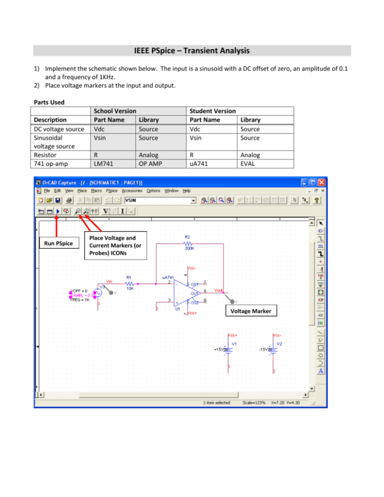
IEEE PSpice – Transient Analysis 1) Implement the schematic shown below. The input is a sinusoid with a DC offset of zero, an amplitude of 0.1 and a frequency of 1KHz. 2) Place voltage markers at the input and output. Parts Used Description DC voltage source Sinusoidal voltage source Resistor 741 op-amp Run PSpice School Version Part Name Library Vdc Source Vsin Source Student Version Part Name Library Vdc Source Vsin Source R LM741 R uA741 Analog OP AMP Analog EVAL Place Voltage and Current Markers (or Probes) ICONs Voltage Marker Performing a Transient Simulation 3) 4) 5) 6) 7) 8) 9) 10) From the top toolbar select Pspice->New Simulation Profile In the pop-up menu that appears type in a simulation name Click on <CREATE> You will see the pop-up menu below Select Transient Analysis as an analysis type Change the run time to 2msec Click <OK> to close the window To run the simulation from the top toolbar select: Pspice-> run OR the Run PSpice icon (see previous page) Plotting After the simulation is complete a new window will appear. Because we placed voltage markers at the inputs and output of the circuit these two voltage traces are automatically plotted. Plotting Additional Traces To plot additional traces after a simulation has run. 11) In the window with the simulation results select: Traces-> Add Trace 12) The pop-up menu below will appear On the left hand side are all the voltages and currents that are available to plot. On the right hand side are mathematical functions that can be performed on these values. The output variables are sensibly named: currents begin with an I, voltages with a V. For example I(R1) is the current going through the resistor R1. 13) Select the current through resistor R1 14) Click <OK> - to close the window and plot the current Deleting Traces 15) Click on the I(IR) icon at the bottom left of the simulation window 16) click <delete> to delete it Cursors After a simulation has run one can use cursors to get precise simulation values. 17) To activate the cursors click on the toggle cursor on icon at the top of the Simulation window (see below) A small Probe Cursor window, shown below, will appear. Next to A1 are x and y values for the left mouse cursor. Next to A2 are values for the right mouse cursor. dif shows the difference between the values for the left and right mouse cursors Toggle cursor on 18) Affiliate left cursor, A1, with the trace of V(VOUT) by clicking on its icon at the bottom of the simulation window with the LEFT mouse button (see below) 19) Affiliate right cursor, A2, with the trace of V(VIN) by clicking on its icon with the RIGHT mouse button (see below) 20) Click on the V(VOUT) trace with the LEFT mouse button to define the position of the A1 cursor. Crosshairs will be shown corresponding X and Y values are displayed in the Probe Cursor window. The crosshairs can be moved by dragging the mouse with the right button. Note: o The position of the A2 cursor is similarly controlled with the right mouse button o The difference between the A1 and A2 cursors is shown in the Probe Cursor menu as well. o Cursors A1 and A2 can be used for the same trace Toggle curser icon left mouse click here Left mouse click Right mouse click AC simulation Delete the voltage probe at the input and replace the Vsin part with either a Vac or Vsrc part from the Source Library. It is possible to add a dc offset to this AC source here we have left it zero. Note that the parameter Vac is one. This is the amplitude of the AC signal. Using an amplitude of one, causes the transfer function to automatically be plotted. R2 200K Vsrc or Vac part from SOURCE Library Vcc- V4 0Vdc 1Vac TRAN = Vcc+ 4 uA741 2 - V- R1 Vin OS1 10K 3 0 0 + V+ OUT OS2 1 +15Vdc 6 5 Vcc- V1 V2 -15Vdc Vout V 0 0 U1 7 Vcc+ Performing an AC simulation 21) 22) 23) 24) 25) 26) From the top toolbar in the schematic window menu select: PSpice ->Edit Simulation Profile In the Simulation Settings window select AC Sweep/Noise as an analysis type Enter the frequency range as shown below DO NOT START with 0, Note that 1M is equivalent to 1m = 10-3 Select Logarithmic instead of linear (This is more customary.) Specify 10 points per decade Click <OK> to close the window Do NOT start at ZERO! 27) To run the simulation from the top toolbar select: Pspice-> run OR click on the Run PSpice icon 28) When the simulation is complete you will see the following output. You can see that the output at 1KHz appears to go to 20Volts even though the amplifier should saturate at +15Volts. 20V 10V 0V 1.0Hz V(VOUT) 10Hz 100Hz 1.0KHz Frequency 10KHz 100KHz 1.0MHz Creating Bode Plots 29) In the top toolbar of the simulation window select: Traces->Add Trace There are a number of functions that are helpful for AC simulations. These, and others are shown on the right panel of the Add Traces window. Below are some helpful functions: Function Function name Phase P() Magnetude M() dB dB() Imaginary Part IMG() Real Part R() 30) Plot the phase of the transfer function by plotting the function P(V(Vout)) as shown below. 31) Click <OK> to close the window and plot the phase Below is a plot of the phase. Remember the gain for low frequencies is -20. This is represented with a180 degree phase shift. 173d 130d 87d 50d 1.0Hz P(V(VOUT)) 10Hz 100Hz 1.0KHz 10KHz 100KHz 1.0MHz Frequency Showing the magnitude as a separate plot (a strip chart) 32) 33) 34) 35) From the top toolbar of the schematic window with the waveforms select: Plot-> Add Plot to Window. From the top toolbar of the simulation window select: Traces->Add Trace Plot the magnitude of the transfer function by plotting the function M(V(Vout)) Click <OK> to close the window and plot. A transient simulation with a digital pulse and initial condition 36) Build the simple RC circuit shown below. Add voltage markers to the input and output. 37) The part IC1 is used to assign an assign the initial condition of 2Volts at the node Vout. PART LIBBARY Resistor R ANALOG Capacitor C ANALOG digital waveform Vpulse SOURCE Initial condition IC1 or IC2 (IC1 shown) SPECIAL + IC= 2V R1 Vin Vout 1k V1 = 0 V2 = 5 TD = 1u TR = 1n TF = 1n PW = 1u PER = 2u V1 V V C1 0.1n 0 Parameter V1 V2 TD TR/TF PW PER Description First Voltage Second Voltage Delay Time Rise/Fall time Pulse width Period There are two parts that are helpful for digital Spice simulations. One is Vpwl and the other is Vpulse. Here we are using Vpulse the parameters necessary for Vpulse are summarized below. 38) Run a Transient simulation simulating from 1-4usec 39) The output should appear as follows 5.0V 2.5V 0V 0s V(VOUT) 0.5us V(VIN) 1.0us 1.5us 2.0us Time 2.5us 3.0us 3.5us 4.0us


