Table 2-4. GOES-11 Imager (Side 1) Coefficients
advertisement
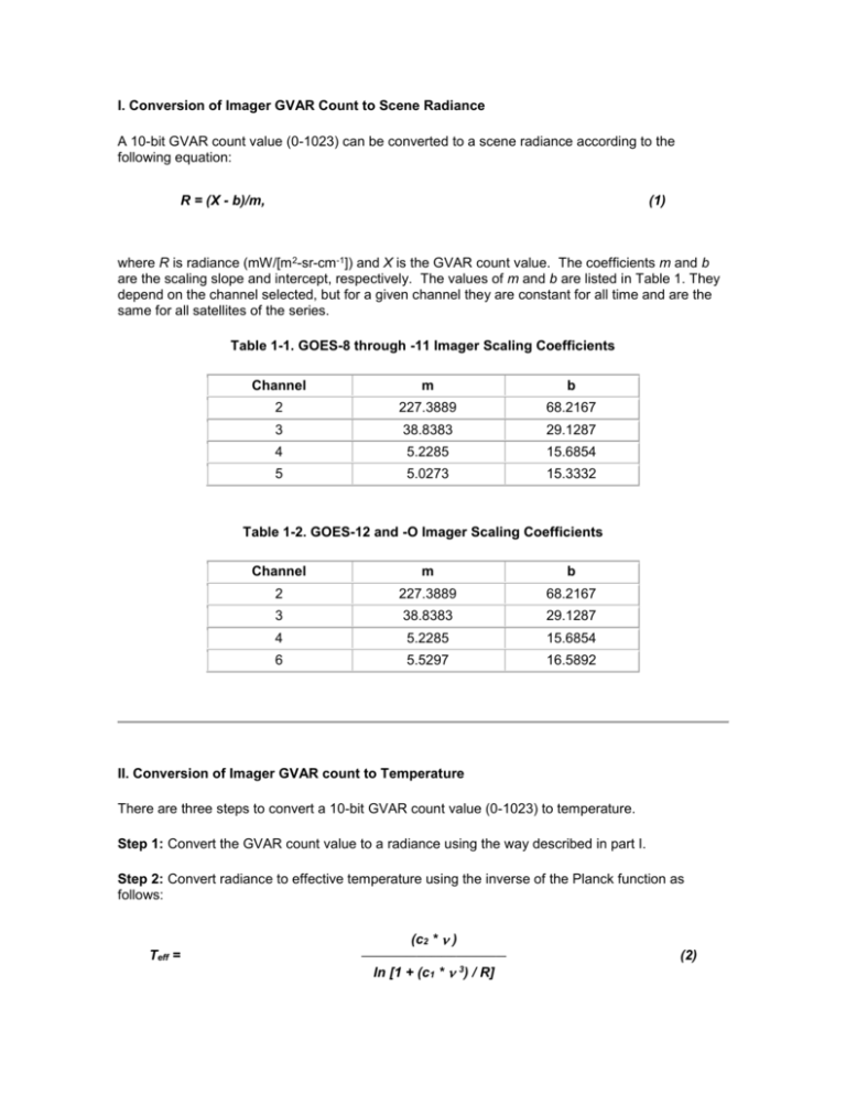
I. Conversion of Imager GVAR Count to Scene Radiance A 10-bit GVAR count value (0-1023) can be converted to a scene radiance according to the following equation: R = (X - b)/m, (1) where R is radiance (mW/[m 2-sr-cm-1]) and X is the GVAR count value. The coefficients m and b are the scaling slope and intercept, respectively. The values of m and b are listed in Table 1. They depend on the channel selected, but for a given channel they are constant for all time and are the same for all satellites of the series. Table 1-1. GOES-8 through -11 Imager Scaling Coefficients Channel m b 2 227.3889 68.2167 3 38.8383 29.1287 4 5.2285 15.6854 5 5.0273 15.3332 Table 1-2. GOES-12 and -O Imager Scaling Coefficients Channel m b 2 227.3889 68.2167 3 38.8383 29.1287 4 5.2285 15.6854 6 5.5297 16.5892 II. Conversion of Imager GVAR count to Temperature There are three steps to convert a 10-bit GVAR count value (0-1023) to temperature. Step 1: Convert the GVAR count value to a radiance using the way described in part I. Step 2: Convert radiance to effective temperature using the inverse of the Planck function as follows: Teff = (c2 * ) _____________________________ ln [1 + (c1 * 3) / R] (2) c1 = 1.191066 x 10⁻⁵ [mW/(m2-sr-cm-4)] c2 = 1.438833 (K/cm-1) where Teff is effective temperature (K), ln stands for natural logarithm, and R is radiance. The coefficients , c1, and c2 are the central wavenumber of the channel and the two radiation constants, respectively. The constants c1 and c2 are invariant, but depends on the spectral characteristics of the channel and will vary from instrument to instrument. Step 3: Convert effective temperature Teff to actual temperature T (K) using the following equation: T = + * Teff (3) where and are two conversion coefficients. Note in the conversions that: The values of (cm-1) in step 2 and constants and in step 3 depend on channel and instrument. Their values are listed below in Tables 2-1 through 2-5. The term side 1 or side 2 in the table headings indicates the operation of one of the two redundant sets of detectors and electronics on each imager. The coefficients , , and depend on the choice of side. The GOES-8, -9, -11, -12 and -13 imagers have always operated on side 1. The GOES-10 imager is operating on side 2. The GOES-O imager is expect to operate on side 1 after launch on April 28, 2009. We will provide the coefficients for other electronics sides when they are needed. Table 2-1. GOES-8 Imager (Side 1) Coefficients Channel/Detector 2/a 2556.71 -0.578526 1.001512 2/b 2558.62 -0.581853 1.001532 3 1481.91 -0.593903 1.001418 4/a 934.30 -0.322585 1.001271 4/b 935.38 -0.351889 1.001293 5/a 837.06 -0.422571 1.001170 5/b 837.00 -0.466954 1.001257 Table 2-2. GOES-9 Imager (Side 1) Coefficients Channel/Detector 2/a 2555.18 -0.579908 1.000942 2/b 2555.18 -0.579908 1.000942 3 1481.82 -0.493016 1.001076 4/a 934.59 -0.384798 1.001293 4/b 934.28 -0.363703 1.001272 5/a 834.02 -0.302995 1.000941 5/b 834.09 -0.306838 1.000948 Table 2-3. GOES-10 Imager (Side 2) Coefficients Channel/Detector 2/a 2552.9845 -0.60584483 1.0011017 2/b 2552.9845 -0.60584483 1.0011017 3 1486.2212 -0.61653805 1.0014011 4/a 936.10260 -0.27128884 1.0009674 4/b 935.98981 -0.27064036 1.0009687 5/a 830.88473 -0.26505411 1.0009087 5/b 830.89691 -0.26056452 1.0008962 Table 2-4. GOES-11 Imager (Side 1) Coefficients Channel/Detector 2/a 2562.07 -0.644790 1.000775 2/b 2562.07 -0.644790 1.000775 3 1481.53 -0.543401 1.001495 4/a 931.76 -0.306809 1.001274 4/b 931.76 -0.306809 1.001274 5/a 833.67 -0.333216 1.001000 5/b 833.04 -0.315110 1.000967 Table 2-5. GOES-12 Imager (Side 1) Coefficients Channel/Detector 2/a 2562.45 -0.650731 1.001520 2/b 2562.45 -0.650731 1.001520 3/a 1536.43 -4.764728 1.012420 3/b 1536.94 -4.775517 1.012403 4/a 933.21 -0.360331 1.001306 4/b 933.21 -0.360331 1.001306 6 751.91 -0.253449 1.000743 Table 2-6. GOES-13 Imager (Side 1) Coefficients Channel/Detector 2/a 2561.74 -1.437204 1.002562 2/b 2561.74 -1.437204 1.002562 3/a 1522.52 -3.625663 1.010018 3/b 1521.66 -3.607841 1.010010 4/a 937.23 -0.386043 1.001298 4/b 937.27 -0.380113 1.001285 6 (ITT original) 753.15 -0.195055 1.000610 6 (ITT updated) 751.93 -0.134688 1.000481 6 749.83 -0.134801 1.000482 (Currently operational, STAR updated) Table 2-7a. GOES-14 Imager (Side 1) Coefficients (Release Rev D, 2005) Channel/Detector 2/a 2572.47 -1.530285 1.002507 2/b 2572.47 -1.530285 1.002507 3/a 1529.33 -3.561161 1.009501 3/b 1530.10 -3.577037 1.009444 4/a 934.04 -0.263369 1.001176 4/b 933.94 -0.260576 1.001179 6/a 753.38 -0.199338 1.000616 6/b 753.91 -0.234004 1.000692 Table 2-7b. GOES-14 Imager (Side 1) Coefficients (Release Rev E, 2008; Operational Nov. 23, 2009) Channel/Detector 2/a 2577.98 -1.596954 1.002631 2/b 2577.98 -1.5969544 1.002631 3/a 1529.35 -3.580129 1.009547 3/b 1530.13 -3.595987 1.009490 4/a 936.20 -0.2875616 1.001258 4/b 936.14 -0.2888648 1.001265 6/a 753.30 -0.1938129 1.000605 6/b 753.84 -0.2296604 1.000684 III. Precision of the Conversion of Imager GVAR Count to Temperature The use of Teff accounts for the variation of the Planck function across the spectral passband of the channel. The differences between the values of T and T eff increase with decreasing temperature. They are usually of the order of 0.1 K. In the worst case, near 180 K, they are approximately 0.3 K. A change of one GVAR count is equivalent to a temperature change of approximately 0.11 K in channels 2,4,5, and 6 for a scene at 300K, and a change of approximately 0.04 K in channel 3 for a scene at 290 K. The errors resulting from the above approximations can be reduced by a factor of 10 if the following second-order polynomial is adopted: T = + * Teff + * Teff2 (4) This yields errors under 0.001 K, even at temperatures above 310 K or under 210 K. The , , and coefficients and centroid wavenumber for all detectors are listed in the tables 3-1a through 3-5a below: Table 3-1: GOES-8 imager Table 3-2: GOES-9 imager Table 3-3: GOES-10 imager Table 3-4: GOES-11 imager Table 3-5: GOES-12 imager Table 3-6: GOES-13 imager Table 3-7: GOES-14 imager
