Supplementary information_resubmission
advertisement
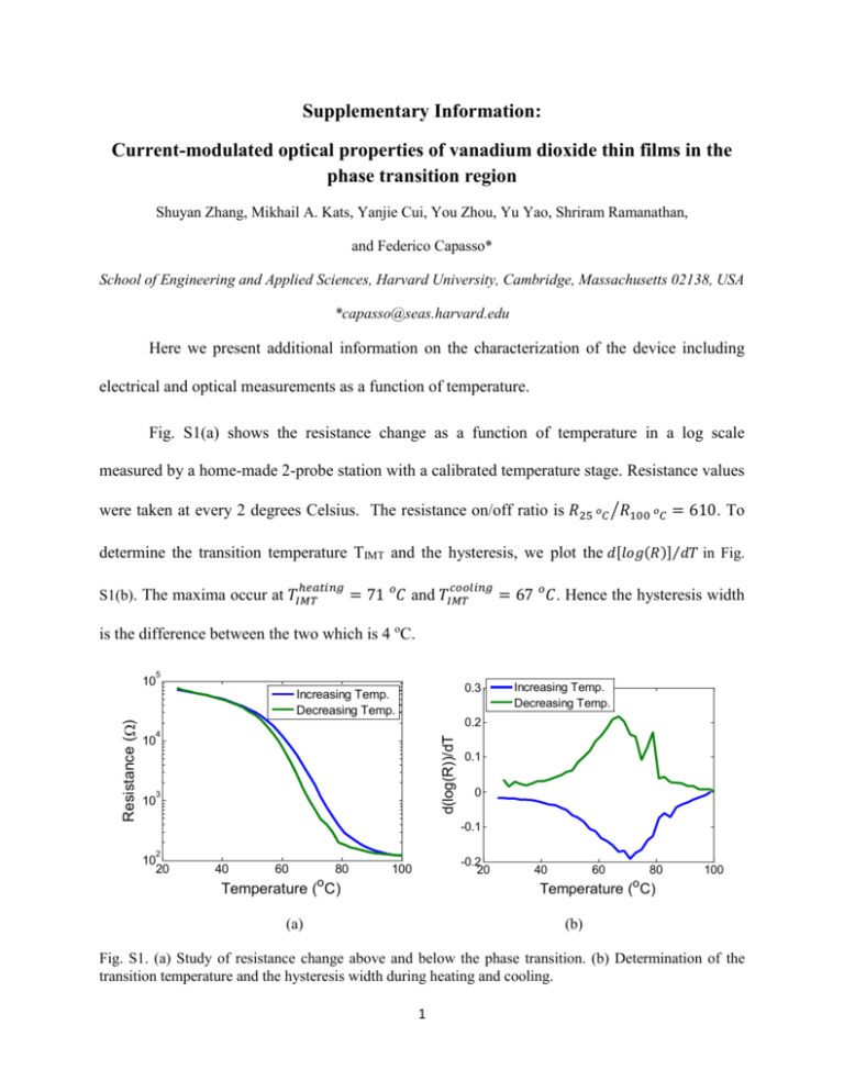
Supplementary Information: Current-modulated optical properties of vanadium dioxide thin films in the phase transition region Shuyan Zhang, Mikhail A. Kats, Yanjie Cui, You Zhou, Yu Yao, Shriram Ramanathan, and Federico Capasso* School of Engineering and Applied Sciences, Harvard University, Cambridge, Massachusetts 02138, USA *capasso@seas.harvard.edu Here we present additional information on the characterization of the device including electrical and optical measurements as a function of temperature. Fig. S1(a) shows the resistance change as a function of temperature in a log scale measured by a home-made 2-probe station with a calibrated temperature stage. Resistance values were taken at every 2 degrees Celsius. The resistance on/off ratio is 𝑅25 𝑜𝐶 ⁄𝑅100 𝑜𝐶 = 610. To determine the transition temperature TIMT and the hysteresis, we plot the 𝑑[𝑙𝑜𝑔(𝑅)]⁄𝑑𝑇 in Fig. ℎ𝑒𝑎𝑡𝑖𝑛𝑔 S1(b). The maxima occur at 𝑇𝐼𝑀𝑇 𝑐𝑜𝑜𝑙𝑖𝑛𝑔 = 71 𝑜𝐶 and 𝑇𝐼𝑀𝑇 = 67 𝑜𝐶 . Hence the hysteresis width is the difference between the two which is 4 oC. 5 10 0.3 Increasing Temp. Decreasing Temp. 0.2 4 d(log(R))/dT Resistance () Increasing Temp. Decreasing Temp. 10 3 10 0.1 0 -0.1 2 10 20 40 60 80 -0.2 20 100 o 40 60 80 100 o Temperature ( C) Temperature ( C) (a) (b) Fig. S1. (a) Study of resistance change above and below the phase transition. (b) Determination of the transition temperature and the hysteresis width during heating and cooling. 1 Fig. S2(a) and (b) show the reflectance spectra at different temperatures for the heating and cooling cycles respectively. The measurements were performed with Bruker Fourier transform infrared (FTIR) spectrometer with a Hyperion 3000 FTIR microscope. Above the TIMT, VO2 is in its metallic phase which has a high reflectance close to 0.6 whereas below the TIMT, VO2 is insulating which has a low reflectance of about 0.2 and it decreases as the wavelength increases. This observation is consistent with Fig. 4(d) in the main article. The close-to-zero reflectance point at about 11.6 µm is a result of critical coupling and is used as the perfect absorber condition discussed in Ref. 1. Unfortunately our Focal Plane Array detector has a limited spectral range, so this feature is not captured in Fig. 4 in the main article. 1 0.6 0.4 0.6 0.4 0.2 0.2 0 90 C 70 C 68 C 67 C 60 C 50 C 23.8 C 0.8 Reflectance 0.8 Reflectance 1 21.6 C 40 C 65 C 70 C 71 C 72 C 80 C 100 C 5 10 0 15 5 10 15 Wavelength(m) Wavelength(m) (a) (b) Fig. S2. Reflectance spectra at different temperatures during the heating cycle (a) and the cooling cycle (b). Reference: 1 M. A. Kats, D. Sharma, J. Lin, P. Genevet, R. Blanchard, Z. Yang, M. M. Qazilbash, D. N. Basov, S. Ramanathan, and F. Capasso, Applied Physics Letters 101 (22) (2012). 2
